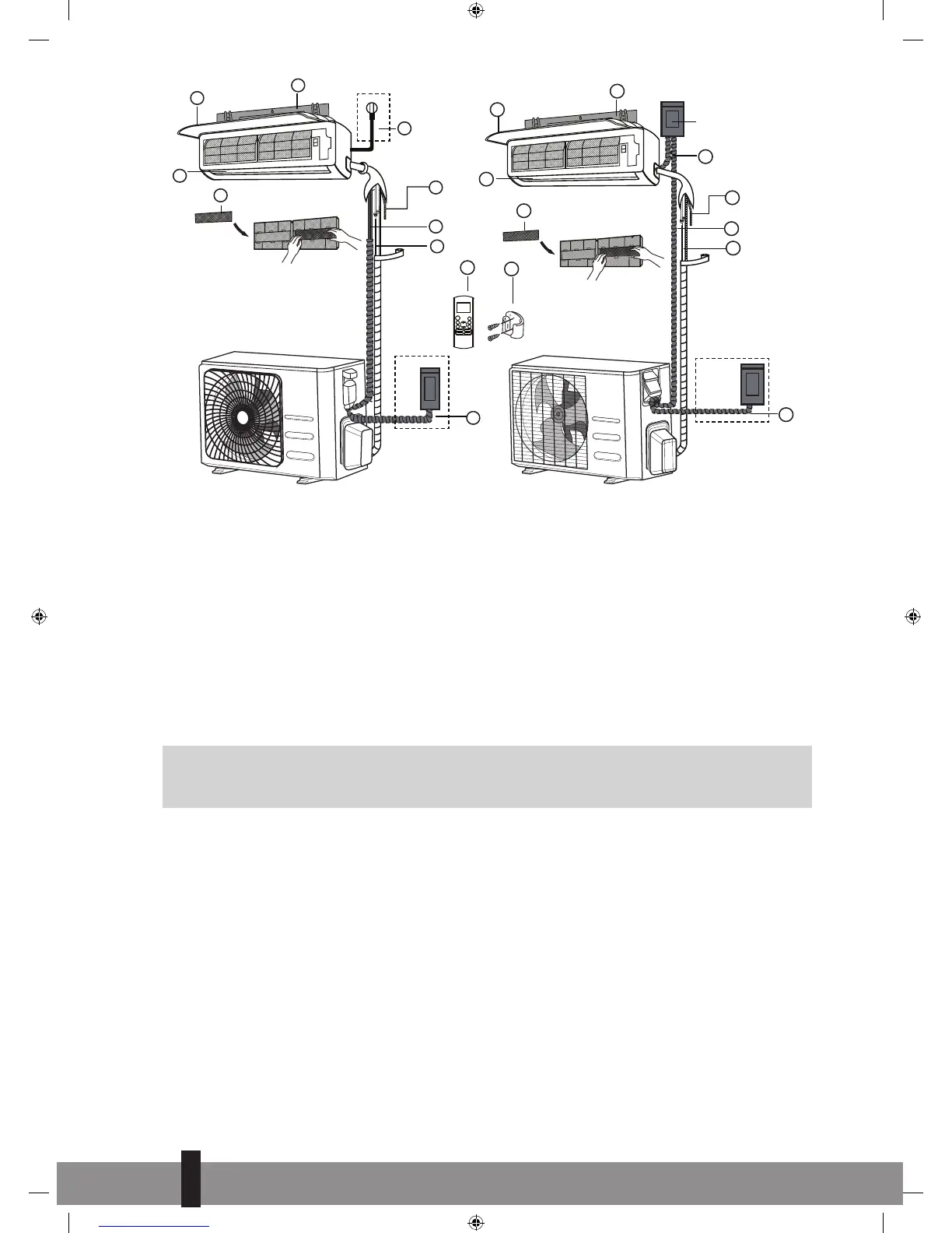
EasyManua.ls Logo

Qlima S-JA2518 User Manual

Qlima S-JA2518
84 pages
Go to English
To Next Page IconTo Next Page
To Previous Page IconTo Previous Page
Page #22 background image
22
Wall Mounting Plate
Power Cable (Some Units)
Refrigerant Piping
Signal Cable
Remote Controller
Drainage Pipe
Louver
Remote controller Holder
(Some Units)
Functional Filter (On Front of
Main Filter - Some Units)
Front Panel
Outdoor Unit Power Cable
(Some Units)
1
2
3
4
5
6
7
8
9
10
11
1 2
1
2
3
4
6
7
8
9
10
11
Air-break switch
3
1
2
4
5
6
7
8
11
5
Figure 1
1. Wall mounting plate
2. Front panel
3. Power cable (some units)
4. Louver
5. Functional filter (on front of
main filter - Some units)
6. Drainage pipe
7. Signal cable
8. Refrigerant piping
9. Remote controller
10. Remote controller holder
(Some units)
11. Outdoor unit power cable
(Some units)
Air-break switch
G
ATTENTION
This illustration is for explanation and indication purposes only. The illustration may be different
from the air conditioner you purchased.
3. ACTIVITIES FOR INSTALLING THE AIR CONDITIONER FOR THE S-JA2518
MODELS
a. Determine the location where the interior unit and exterior unit can be installed. See chapter 5 and 6.
b. Mount the mounting plate of the interior unit. See chapter 7.1.
c. Drill a hole to outside that the lines can be fed through. See chapter 7.2.
d. Hang the interior unit, by the hooks on the back, on the top hooks of the mounting plate and check
that it is securely mounted. Do not click the bottom hooks in yet.
4
22
Q_instal_S-JA2518 ('17) V2.indd 22 30-10-17 14:42
Question and Answer IconNeed help?

Do you have a question about the Qlima S-JA2518 and is the answer not in the manual?

Qlima S-JA2518 Specifications

General IconGeneral
BrandQlima
ModelS-JA2518
CategoryAir Conditioner
LanguageEnglish

Summary

1. Safety Precautions

2. Items Packed with the Unit

3. Activities for Installing the Air Conditioner for the S-JA2518 Models

4. Determining the Location of the Inside and Outside Unit

4.1 Determining the location of the inside and outside unit for the S-JA2518 models

Guidance on selecting indoor and outdoor unit placement.

4.2 Determining the location of the exterior unit for the S-JA2518 models

Guidelines for positioning the outdoor unit, considering noise and clearance.

5. Possibilities for Installing the Piping from the Interior Unit to the Exterior Unit

6. Mounting the Installation Plate and Making the Piping Feedthrough

6.1 Mounting the installation plate of the interior unit

Instructions for securely attaching the indoor unit's mounting plate to the wall.

6.2 Drilling the piping, condensation hose and cable feed-through

Details on drilling holes through the wall for unit connections.

7. Connecting the Coolant Pipes

7.1 Connecting the coolant pipes for the S-JA2518 models

Steps for properly connecting refrigerant pipes to indoor and outdoor units.

8. Connection the Condensation Drainage Hose for the S-JA2518 Models

8.1 Connection the condensation discharge hose to the interior unit

How to connect the drain hose to the indoor unit and ensure proper drainage.

8.2 Drain joint installation

Instructions for fitting the drain joint to the outdoor unit for condensate removal.

9. Electrical Work

10. Connecting the Electrical Cables

11. Evacuating the Cooling System of the S-JA2518 Models

12. Check for Coolant Leakage for the S-JA2518 Models

13. Topping Up Coolant for Piping Lengths Above 05 Metres

14. Test Running After Installation

Related product manuals