2 – General Description
Chassis Controls and LEDs
59225-00 B 2-3
A
2.1.1.2
Placing the Switch in Maintenance Mode
To place the switch in maintenance mode, do the following:
1. Isolate the switch from the fabric.
2. Press and hold the Maintenance button with a pointed tool. When the
Heartbeat LED alone is illuminated, release the button. The Heartbeat LED
illuminates continuously while the switch is in maintenance mode.
To exit maintenance mode and return to normal operation, momentarily press and
release the Maintenance button to reset the switch.
2.1.2
Chassis LEDs
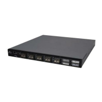
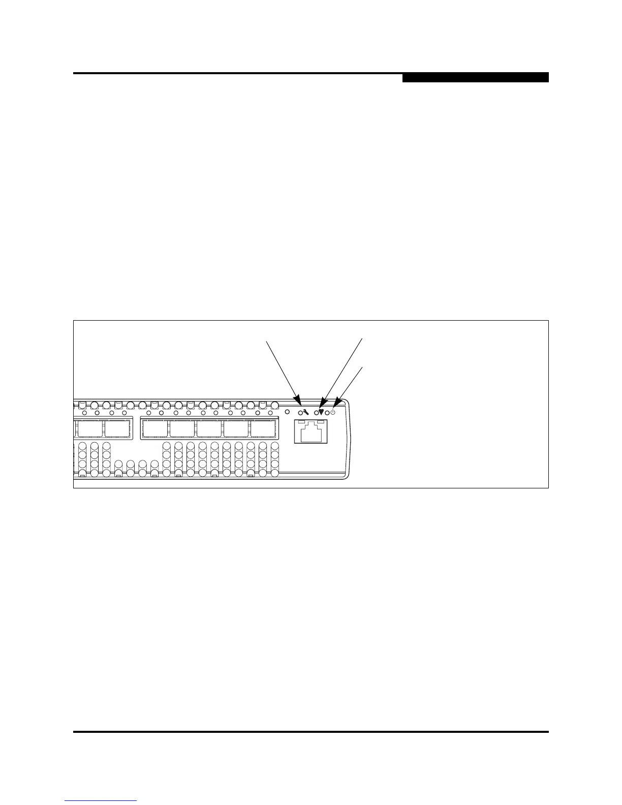
The chassis LEDs shown in Figure 2-3 provide status information about switch
operation. Refer to “Port LEDs” on page 2-5 for information about port LEDs.
Figure 2-3. Chassis LEDs
2.1.2.1
Input Power LED (Green)
The Input Power LED indicates the voltage status at the switch logic circuitry.
During normal operation, this LED illuminates to indicate that the switch logic
circuitry is receiving the proper DC voltages. When the switch is in maintenance
mode, this LED is extinguished.
L A L A L A L A
L A L A L A
3 4 5 6 7 8 9
System Fault LED
(Amber)
Heartbeat LED
(Green)
Input Power LED
(Green)
 Loading...