Use r’ s M a nual
Jumper Settings
To ensure correct system configuration, the following section describes how to set
the jumpers to enable/disable or change functions. For jumper descriptions, please
refer to the table below.
Table 2 Jumper List
Labe
Function
JP1 Panel & Backlight Power Selection for LVDS1
JP2 Backlight Power Enable Selection for LVDS1
JP3
T / ATX Mode Selection
JP4 LVDS1_ Backlight DC/PWM Selection
JP5 Signal / Power Selection for COM5
JP6 Signal / Power Selection for COM6
JP7 Signal / Power Selection for COM3
JP8 Signal / Power Selection for COM4
JP9 ME F/W Selection
JP1
MPCIE Activity LED Indication
JP11 Signal / Power Selection for COM2
JP1
Signal / Power Selection for COM1
JP1
RTC Reset Selection
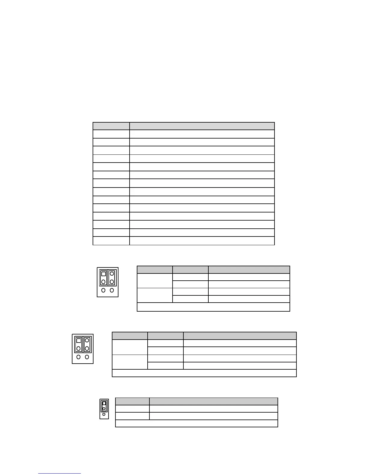
Table 3 JP1 Panel & Backlight Power Selection for LVDS1
21
65
Jumpe
Status
1
1-3 Backlight Pow er = +12
3-5 Backlight Pow er = +5
2
2-4 Panel Pow er = +3.3V
4-6 Panel Pow er = +5V
Pitch:2.54mm [Y IMTEX 3362*03SAGR]
Table 4 JP2 Backlight Power Enable Selection for LVDS1
21
65
Jumpe
Status
1
1-3 Backlight Enable Voltage = +3.3V
3-5 Backlight Enable Voltage = +5V
2
2-4
ctive Low
Pitch: 2.54mm [Y IMTEX 3362*03SAGR]
Table 5 JP3 AT / ATX Mode Selection
2
3
1
Jumpe
T Mode
Pitch:2.54mm [YIMTEX 3321*03SAGR(6T)]
 Loading...