Use r’ s M a nual
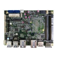
Table 12 ATX1 4-pin ATX Power Input Connector
Pin Signal Name
1 GND
2 GND
3 +12V
4 +12V
Pitch:4.2mm [Y IMTEX 576MWA2*02STR]
Table 13 BAT1 CR2032 Battery Holder
[FOXCONN BB3320E-1]
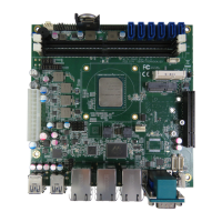
Table 14 COM3~COM6 RS-232 Port 4~10 Pin Header
9
21
Pin Signal
1 DCD, Data carrier detect
/ +12V / +5V *
2 RXD, Receive data
3 TXD, Trans mit data
4 DTR, Data ter minal ready
5 GND, ground
6 DSR, Data set ready
7 RTS, Request to send
8 CTS, Clear to send
9 RI, Ring indicator
/ +12V / +5V *
10 NC, Key
Pitch:2.54mm [Y IMTEX 32510SAG1R(6T)]
*:Selected by JP11~JP17.
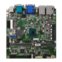
Table 15 CN1 Panel Backlight Wafer for LVDS1
Pin Signal Name
1
BL_PWM
-07T1-V]
*:BL_PWM & BL_ADJ can be setting can be selected by JP4
#
BL_PWM & BL_ADJ can be s etting from 0V to 5V in BIOS s etup
**:Backlight Power can be selected by JP1.
***:BL_EN can be selected by JP2.
 Loading...