GND
[UDE RU1-161F9WGF(XB)]
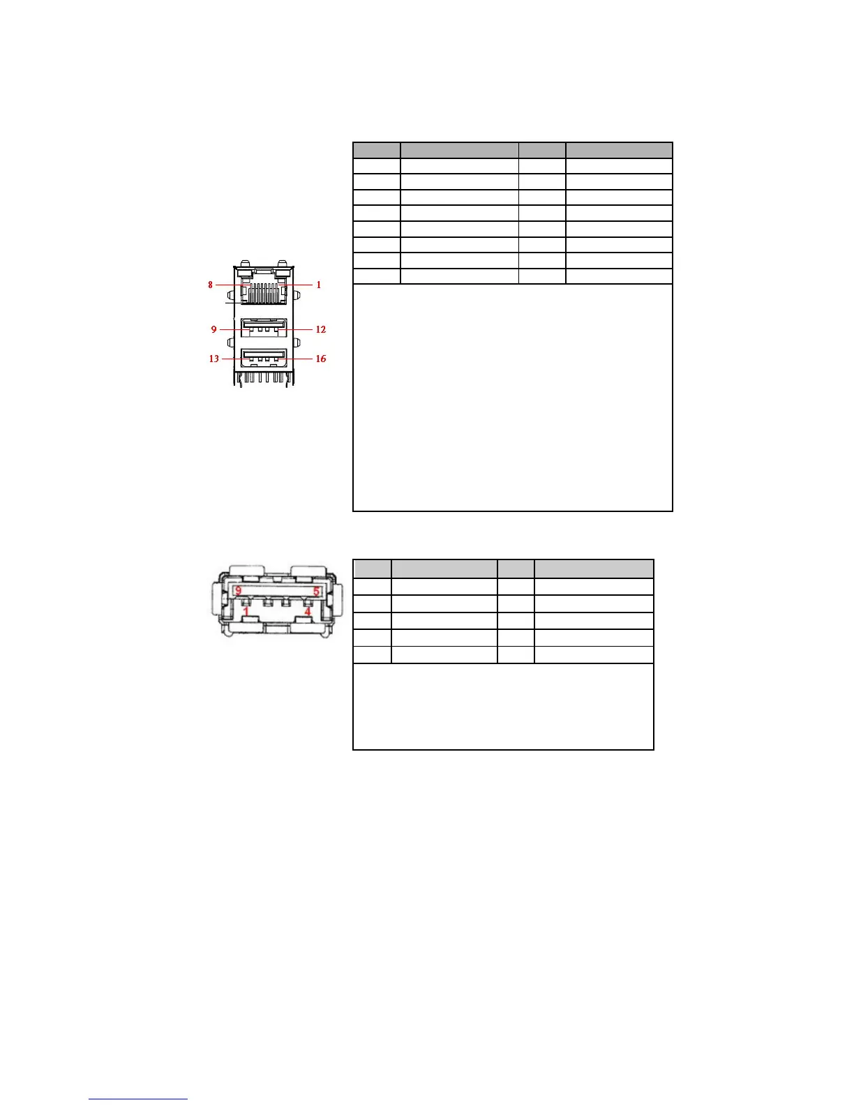
Note:LAN LED Configuration
1. Left (Link) LED:Green / Orange
Link 1000 Orange LED on
Link 100 Green LED on
Link 10 or No Link LED off
2. Right (Active) LED:Yellow
Acti vi t y Yellow LED blink
Table 39 USB1 USB3.0 Port 0 Connector
Pin Signal Name Pin Signal Name
1 +USBVCC * 5 USB_ R
 Loading...