Use r’ s M a nual
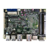
Tabl e 6 JP4 LVDS1_ Backli ght DC/PWM Selecti on
2
3
1
Jumper Status
1-2 Short DC Mode
2-3 Short PWM Mode
Pitch:2.0mm [Y IMTEX 3291*03SAGR(6T)]
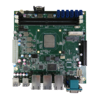
Table 7 JP5~JP8,JP11,JP12 Signal / Power Selection for COM1~COM6
10
1
9
2
Jumpe
Setting Function
1
1-3 Shor
Pin 9 = RI
Pitch:2.54mm [Y IMTEX 3322*05SAGR(6T]
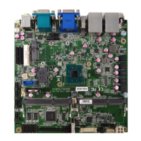
Table 8 JP9 ME F/W Selection
1
2
Jumpe
Status
1-2 Open Normal Operation
1-2 Short
ME F/W Disabled
Pitch:2.54mm [YIMTEX 3321*02SAGR(6T)]
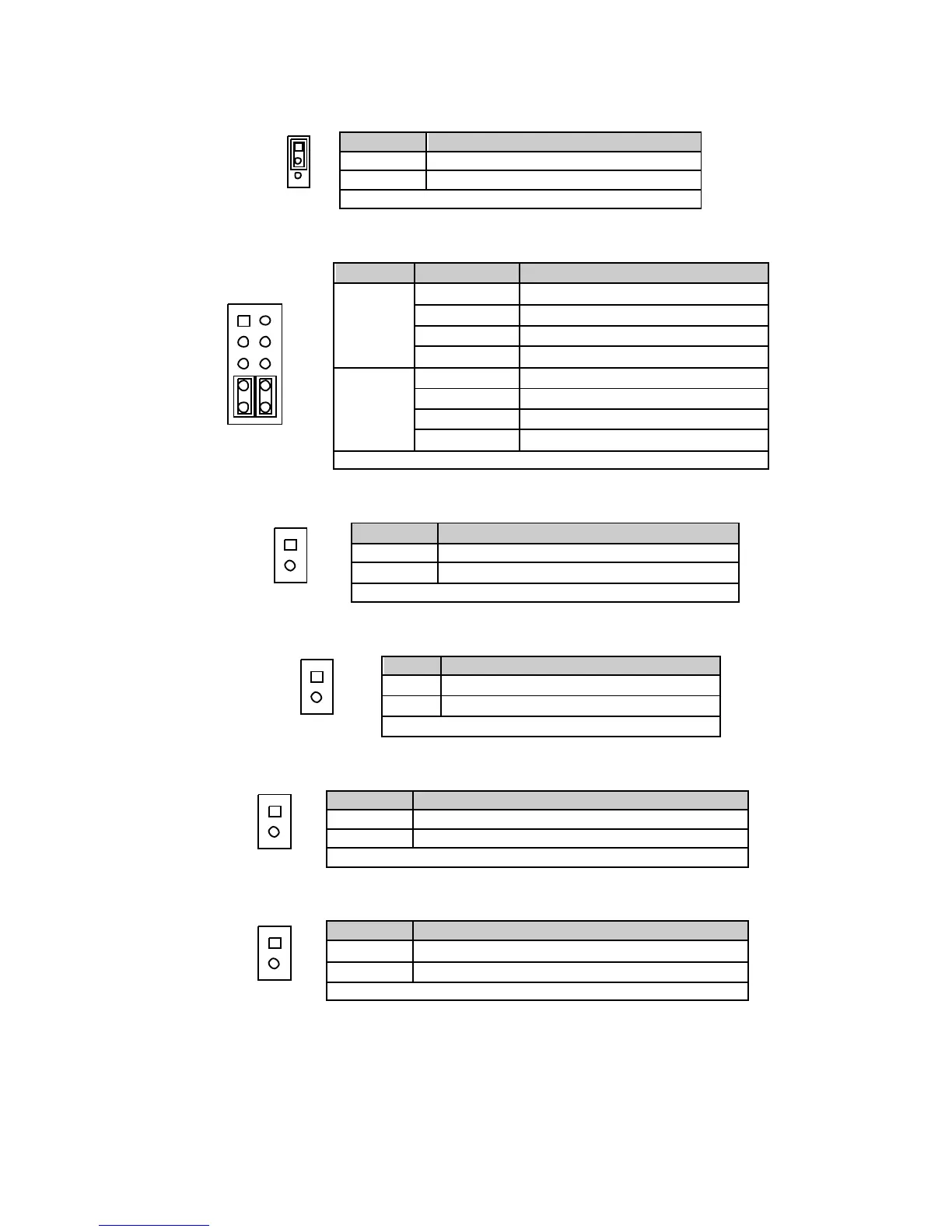
Table 9 JP10 MPCIE Activity LED Indication
1
2
Pin Description
1 LED+
2 LE
-
Pitch:2.54mm [Y IMTEX 3321*02SAGR(6T)]
Tabl e 10 JP13 USB Power Sel ectio n
1
2
Jumpe
Status
1-2 Open USB pow er w ill be cut off in S4 & S5 state.
1-2 Short USB pow er is alw ays supply.
Pitch:2.54mm [YIMTEX 3321*02SAGR(6T)]
Table 11 JP15 RT C Reset Selection
1
2
Jumpe
Status
1-2 Open
Normal Operation
1-2 Short
Clear RTC CMOS
Pitch:2.54mm [YIMTEX 3321*02SAGR(6T)]
 Loading...