EasyManuals Logo

Quanmax KEMX-1750 series User Manual

Quanmax KEMX-1750 series
62 pages
To Next Page IconTo Next Page
To Previous Page IconTo Previous Page
Page #29 background imageLoading...
Page #29 background image
Chapter 2
29
KEMX
-
1
7
50 serie
s
Use r’ s M a nual
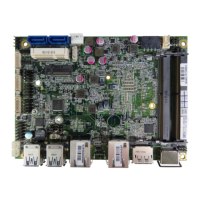
Table 26 FAN2 System FAN Wafer
1
3
2
Pin Signal
1 GND
2 +12V*
3 F
A
N_RPM
Pitch: 2.54mm WAFER [YIMTEX 521AW1*03ST-1R]
*PWM Fan control supported.
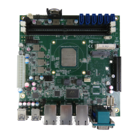
Table 27 FP1 Front Panel 1 Pin Header
-
+
SP KR
+
7
8
HLED
21
-
+
RS TBTN
-
Pin Si
g
na
l
Pin Si
g
na
l
1 Reset Button
+
2 Speaker
+
3 Reset Button
-
4 NC
5 HDD LED + 6 Internal Speake
r
-
7 HDD LED
-
8 Speaker
-
DIP 8P 2R MALE STRAIGHT TYPE Pitch:2.54mm
[YIMTEX 3322*04SAGR(6T)]
NoteInternal Buzzer is enabled w hen Pin6-8 is shorted
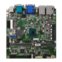
Table 28 FP2 Front Panel 2 Pin Header
+
KLOCK
PLED
2
-
-
9
+
SMC-
SMD
10
+1
PWRBTN
Pin Signal Pin Signal
1 Pow er LED + 2 Pow er Button +
3 NC 4 Pow er Button -
5 Pow er LED - 6 NC
7 Keyboard Loc
k
8 SMBus Data
9 GND 10 SMBus Clock
Pitch:2.54mm [Y IMTEX 3322*05SAGR(6
T
]
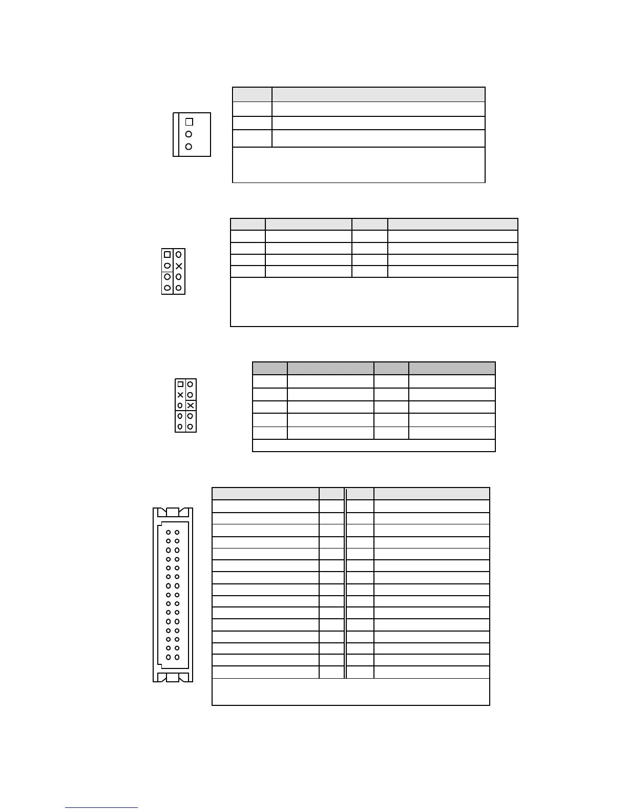
Table 29 LVDS1 Primary 24-bit, 1-channel LVDS Panel Connector
29
2
30
1
Si
g
nal Nam
e
Pin Pin Si
g
nal Nam
e
GND 2 1 VDD_EN
+3.3V / +5V
*
4 3 +3.3V / +5V
*
6 5 Txcl
k
A
-
8 7 Txcl
k
A
+
GND 1
0
9 GND
1
2
11 T xout
A
0
-
14 1
3
Txout
A
0
+
1
6
1
5
Txout
A
1
-
1
8
1
7
Txout
A
1
+
2
0
1
9
Txout
A
2
-
2
2
21 Txout
A
2
+
24 2
3
Txout
A
3
-
2
6
2
5
Txout
A
3
+
GND 2
8
2
7
GND
DDC
_
CLK 3
0
2
9
DDC
_
Dat
a
Pitch:1.25mm Tin Plated [HIROSE DF13-30D
P
-1.25(24)]
*LVDS1 panel pow er can be selected by JP4.

Table of Contents

Questions and Answers:

Question and Answer IconNeed help?

Do you have a question about the Quanmax KEMX-1750 series and is the answer not in the manual?

Quanmax KEMX-1750 series Specifications

General IconGeneral
BrandQuanmax
ModelKEMX-1750 series
CategoryMotherboard
LanguageEnglish

Related product manuals