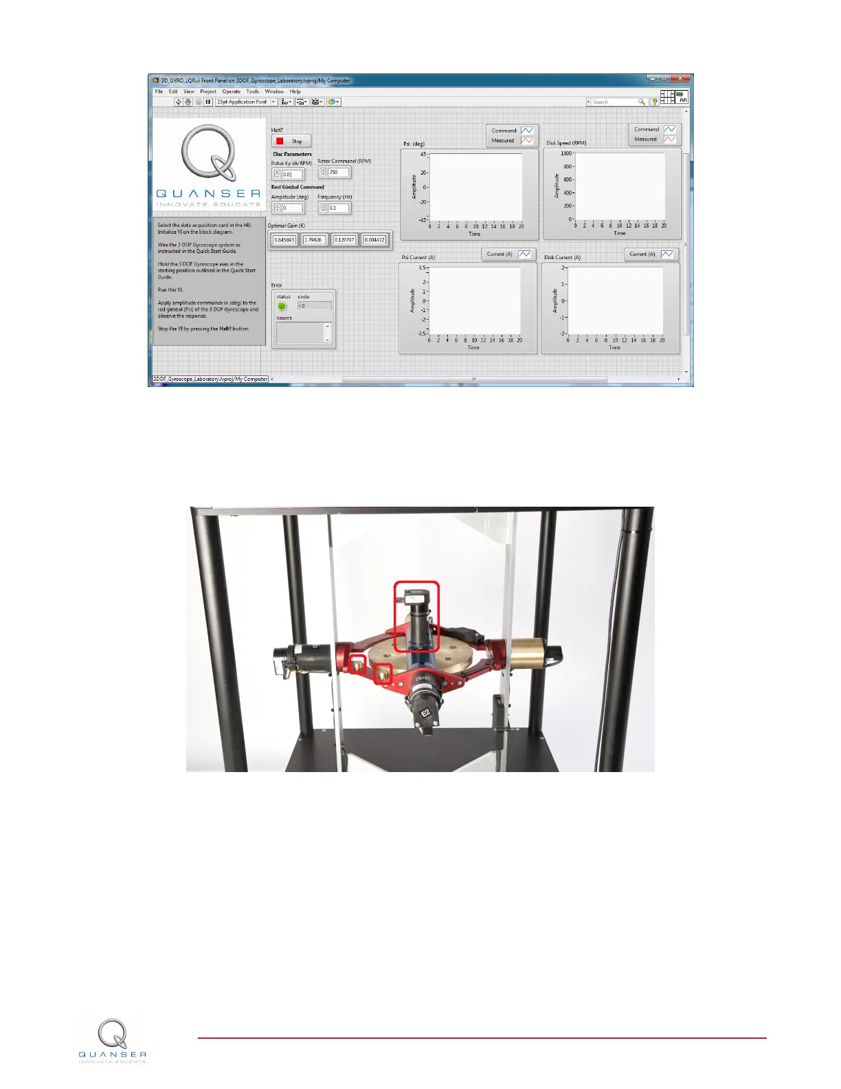
Figure 3.3: VI used to run controller on the 3D GYRO.
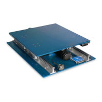
1. Place the 3 DOF Gyroscope flywheel, blue and red gimbals in their home starting position. Ensure that the
flywheel's motor and the mass counter balances on the red gimbal (identified with red squares in Figure 3.4)
are pointing toward the same direction (e.g., all facing up or all facing down).
Figure 3.4: Starting position for the 3D GYRO.
2. You will need to gently hold on to the blue and red gimbals and keep them in place for the first few seconds
after the VI has started running while the flywheel speeds up tp the required RPM as show in Figure 3.5
3. Make sure the VI is set to use the same gain K found in the simulation in Section 3.1. See Section 4 for more
information.
4. Set the Frequency control in the VI front panel to 0.1 Hz.
5. Run the VI by clicking on the white arrow found in the top left hand corner of the VI (CTRL+R) while holding
the blue and red gimbals in their home position as instructed above.
6. Monitor the flywheel speed in the Disc Speed scope. Once it reaches the commanded speed (e.g., 750 RPM),
set the Amplitude control to 20 degrees. This will generate a ±20 degree 0.1 Hz square wave reference.
3D GYRO Laboratory Guide
v 1.1