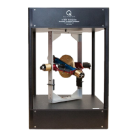
Figure 3.5: Holding the blue and red gimbals
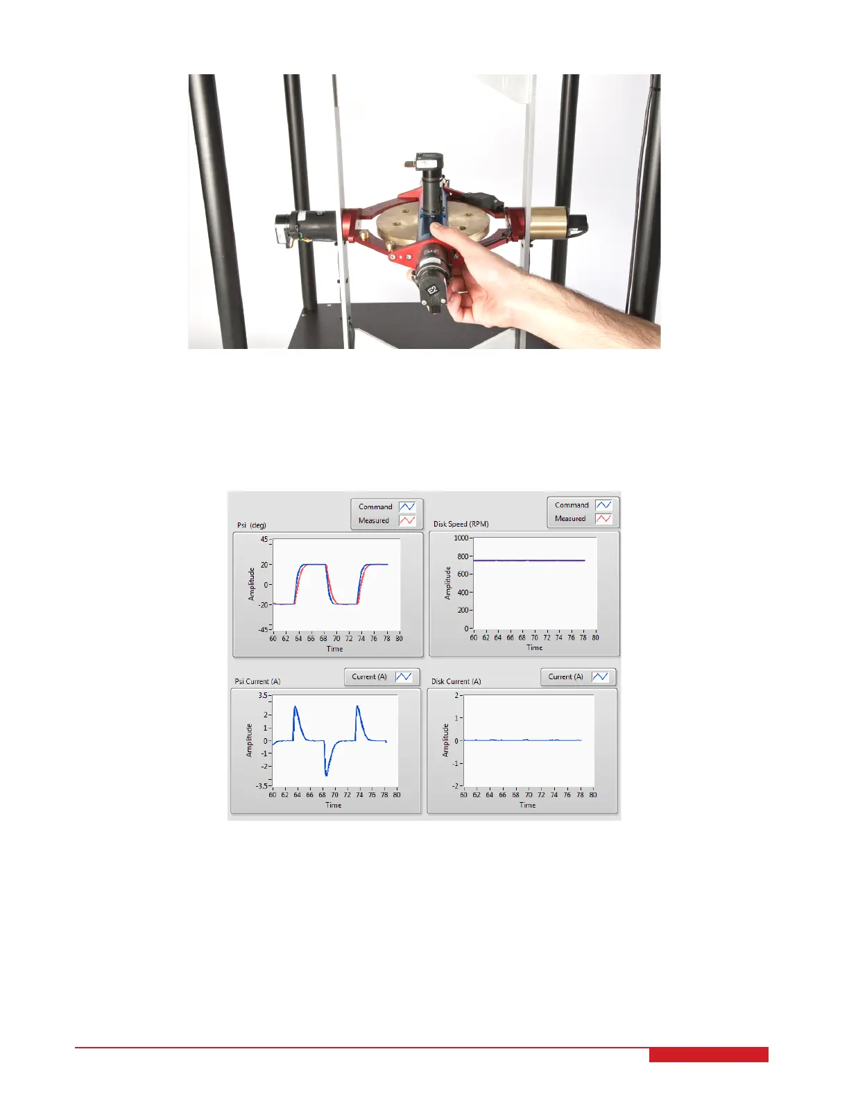
7. The red gimbal should now be going back and forth between the commanded positions at the frequency
specified. Examine the position of the red gimbal in the Psi scope. You can also view the commanded motor
currents in the Disk Current and Psi Current scopes. The scopes should be displaying responses similar to
Figure 3.6.
Figure 3.6: Typical response when running control on 3D GYRO system
3D GYRO Laboratory Guide 12