3 LAB EXPERIMENTS
3.1 Simulation
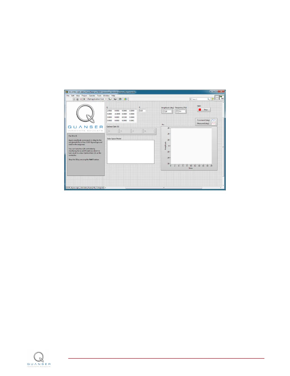
In this section we will use the LabVIEW VI shown in Figure 3.1 to simulate the closed-loop control of the 3 DOF
Gyroscope system. The VI uses the state-feedback control described in Section 2.2.4. The feedback gain K is
found using the LQR VI from the LabVIEW Simulation and Control Design Module (LQR is described briefly in
Section 2.2.3).
Figure 3.1: VI used to simulate the 3 DOF Gyroscope.
IMPORTANT: Before you can conduct these experiments, you need to make sure that the lab files are configured
according to your setup. If they have not been configured already, then you need to go to Section 4 to configure the
lab files first.
3.1.1 Procedure
Follow these steps to simulate the 3 DOF Gyroscope:
1. Open and run the 3D_GYRO_LQR_SIM.vi as described in Section 4.
2. By default, the Q matrix is sent to identity matrix. Set the LQR weighting matrices in to
Q =
2 0 0 0
0 16 0 0
0 0 0.01 0
0 0 0 0.0001
and R = 5.
3. This automatically generates the gain
K =
0.65 1.79 0.12 0.004
.
3D GYRO Laboratory Guide
v 1.1