NB-IoT Module Series
BC66 Hardware Design
BC66_Hardware_Design 27 / 59
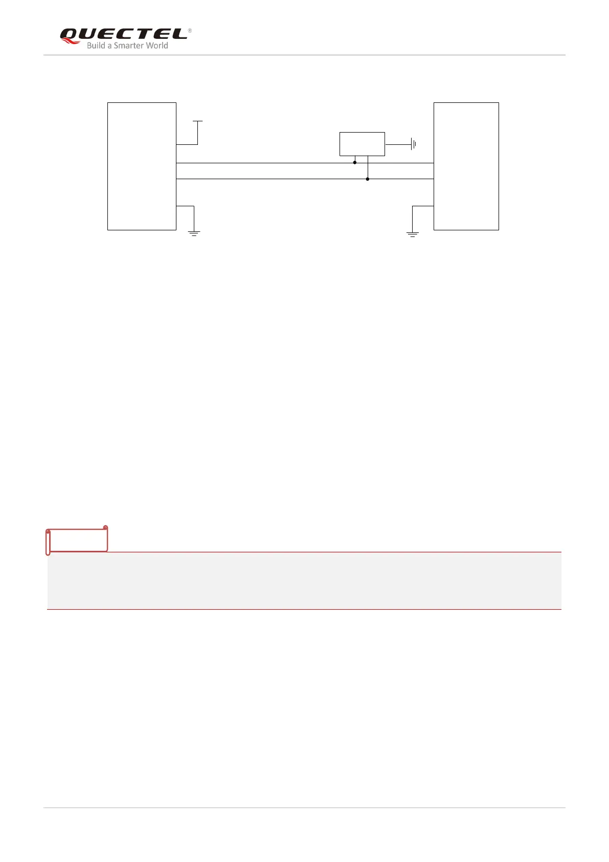
USB_DP
USB_DM
GND
USB_DP
USB_DM
GND
ESD Array
Module
PC
VUSB_3V3
3.3V
Figure 14: USB Interface Reference Design
In the circuit design of USB interface, in order to ensure the performance of USB, the following principles
are suggested in the circuit design:
It is important to route the USB signal traces as differential pairs with ground surrounded. The
impedance of USB differential trace is 90Ω.
Do not route signal traces under power supply, RF signal traces and other sensitive signal traces. It is
important to route the USB differential traces in inner-layer of the PCB, and surround the traces with
ground on that layer and ground planes above and below.
Junction capacitance of the ESD protection device might cause influences on USB data lines, so
please pay attention to the selection of the device. Typically, the stray capacitance should be less
than 3pF.
Keep the ESD protection devices as close to the USB connector as possible.
1. USB_MODE must be pulled down so as to realize USB download function.
2. When the USB interface is used for log capturing, the module will not be able to enter Deep Sleep.
3. When using USB function of the module, an external 3.3V power supply should be provided.
3.9. UART Interfaces
The module provides three UART ports: main UART port, debug UART port and auxiliary UART port. The
module is designed as DCE (Data Communication Equipment), following the traditional DCE-DTE (Data
Terminal Equipment) connection.