NB-IoT Module Series
BC66 Hardware Design
BC66_Hardware_Design 22 / 59
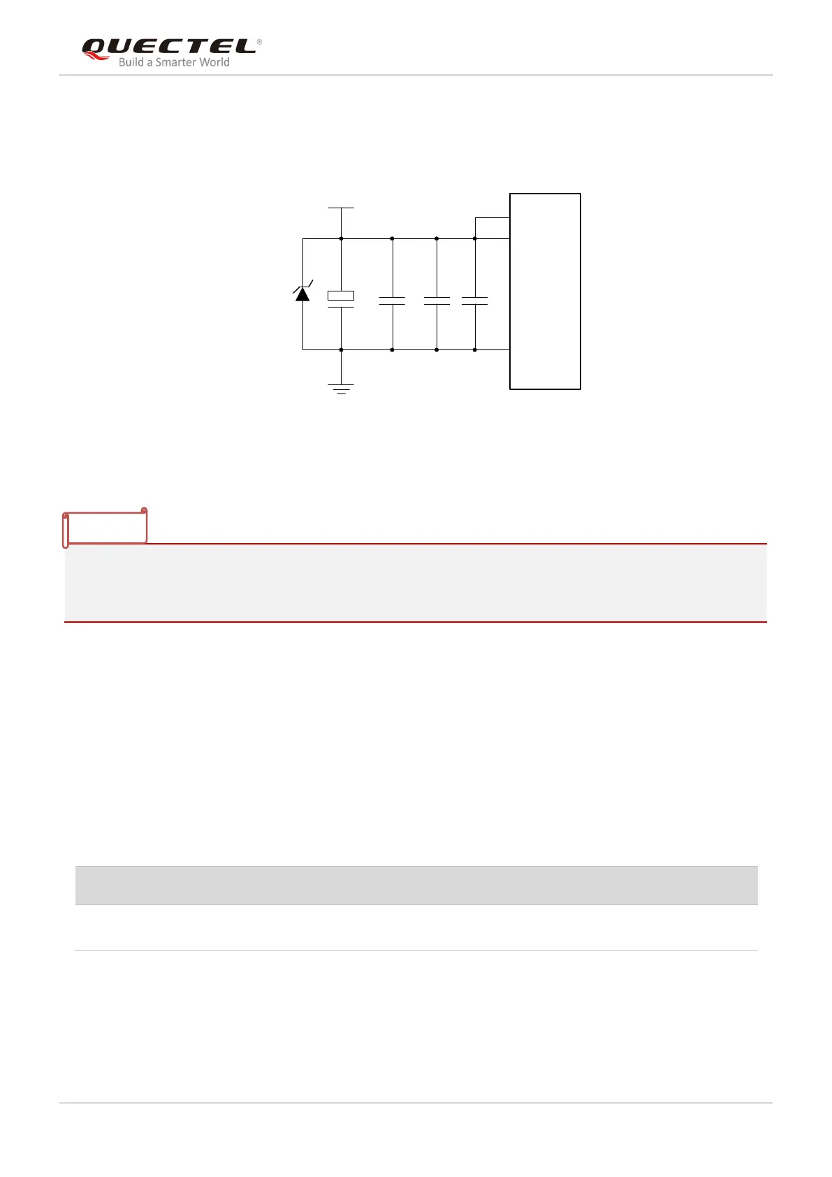
withstand capability. In principle, the longer the VBAT trace is, the wider it should be. A reference circuit
for power supply is illustrated in the following figure.
VBAT
C2C1
+
C3 C4
GND
100uF 100nF 100pF 22pF
VBAT_RF
Module
GND
D1
VBAT_BB
TVS
Figure 5: Reference Circuit for Power Supply
During the module’s power-on or reset, an instantaneous current of 700mA will be generated for a period
of 200us. To decrease the current, it is recommended to connect a large-capacitance capacitor to VBAT. If
the load capacity of power supply is insufficient, then a 100μF tantalum capacitor is recommended.
3.7. Turn on/off Scenarios
3.7.1. Turn on
BC66 can be turned on by driving PWRKEY low for at least 500ms.
Table 9: PWRKEY Pin Definition
Pull down PWRKEY to power
up the module
It is recommended use an open drain/collector driver to control the PWRKEY. A simple reference circuit is
illustrated in the following figure.