LTE-A Module Series
EG060V-EA Hardware Design
EG060V-EA_Hardware_Design 38 / 82
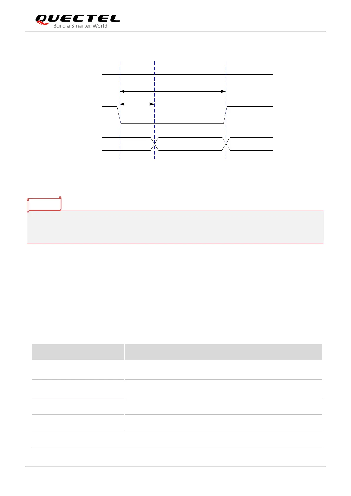
The timing of reset is illustrated in the following figure.
V
IL
≤ 0.5 V
V
IH
≥ 1.3 V
VBAT
≥ 250 ms
Resetting
Module
Status
Running
RESET_N
Restart
≤ 600 ms
Figure 17: Timing of Resetting the Module
1. Reset the module with RESET_N pin only when the module fails to be turned off by AT+QPOWD
command or the PWRKEY pin.
2. Ensure that there is no large capacitance on PWRKEY and RESET_N pins.
3.9. (U)SIM Interface
The (U)SIM interface circuitry meets ETSI and IMT-2000 requirements. Either 1.8 V or 3.0 V (U)SIM cards
is supported.
Table 9: Pin Definition of (U)SIM Interface
Either 1.8 V or 3.0 V is supported
by the module automatically.
(U)SIM card hot-plug detect