EasyManuals Logo

Quectel LTE-A Series User Manual

Quectel LTE-A Series
83 pages
To Next Page IconTo Next Page
To Previous Page IconTo Previous Page
Page #44 background imageLoading...
Page #44 background image
LTE-A Module Series
EG060V-EA Hardware Design
EG060V-EA_Hardware_Design 43 / 82
The logic levels are described in the following table.
Table 13: Logic Level Parameters of Digital I/O
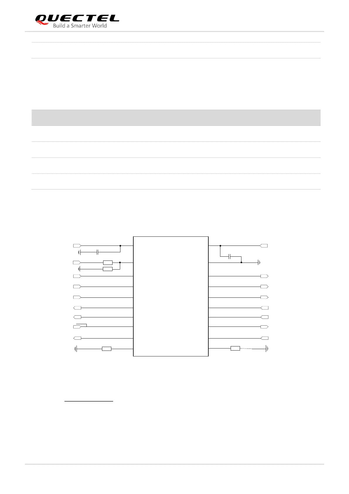
The module provides 1.8 V UART interfaces. A level translator should be used if the application is
equipped with a 3.3 V UART interface. A level translator TXS0108EPWR provided by Texas Instruments
is recommended. Below is a reference design.
VCCA VCCB
OE
A1
A2
A3
A4
A5
A6
A7
A8
GND
B1
B2
B3
B4
B5
B6
B7
B8
VDD_EXT
MAIN_RI
MAIN_DCD
MAIN_RTS
MAIN_RXD
MAIN_DTR
MAIN_CTS
MAIN_TXD
51K
51K
0.1 μF
0.1 μF
RI_MCU
DCD_MCU
RTS_MCU
TXD_MCU
DTR_MCU
CTS_MCU
RXD_MCU
VDD_MCU
Translator
VDD_EXT
10K
120K
Figure 21: Reference Design of Translator Chip
Please visit http://www.ti.com for more information on the recommended translator.
Another approach to level translation is with a transistor translation circuit. A reference design in this
regard is shown below. For the design of circuits shown by dotted lines, both input and output circuit
designs, refer to the circuits shown by the solid lines, but please pay attention to the direction of
connection.
DBG_RXD
136
DI
Debug UART receive
1.8 V power domain
Item
Min.
Max.
Unit
V
IL
-0.3
0.6
V
V
IH
1.2
2.0
V
V
OL
0
0.45
V
V
OH
1.35
1.8
V

Table of Contents

Questions and Answers:

Question and Answer IconNeed help?

Do you have a question about the Quectel LTE-A Series and is the answer not in the manual?

Quectel LTE-A Series Specifications

General IconGeneral
BrandQuectel
ModelLTE-A Series
CategoryControl Unit
LanguageEnglish

Related product manuals