Smart LTE Module Series
Smart EVB G2 User Guide
Smart_EVB_G2_User_Guide Confidential / Released 33 / 59
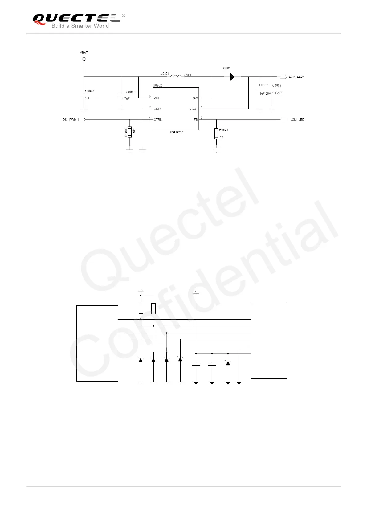
Figure 19: Reference Circuit Design for Backlight Driver
Touch Panel Interfaces 4.4.
The Smart EVB G2 provides two touch panel interfaces. J0804 is the connector for the connection
between touch panel of main LCM interface and Smart EVB G2, and J0802 is the connector for the
connection between touch panel of secondary LCM interface and Smart EVB G2. The following figure
shows a reference circuit design for touch panel interfaces.
TP_ RST
TP_I2C_ SCL
TP_I2C_ SDA
TP_ INT
1
2
3
4
5
6
2.2K
2.2K
LDO 6_1V8
4.7uF
100nF
Module
TP_RST
TP_SCL
TP_SDA
TP_INT
GND
VDD
TP
R2
R1
C1 C2
D1 D2
D3
D4
D5
LDO10_2V8
Figure 20: Reference Circuit Design for Touch Panel Interfaces
The following figure shows the pin assignments of touch panel interfaces, and the following table shows
the pin definition of touch panel interfaces.