Smart LTE Module Series
Smart EVB G2 User Guide
Smart_EVB_G2_User_Guide Confidential / Released 44 / 59
UART Interfaces 4.9.
Smart EVB G2 provides two UART interfaces: main UART port J1401 and debug UART port J1402. The
main UART interface can be used for data transmission and AT command communication. And the debug
UART interface is used for debugging.
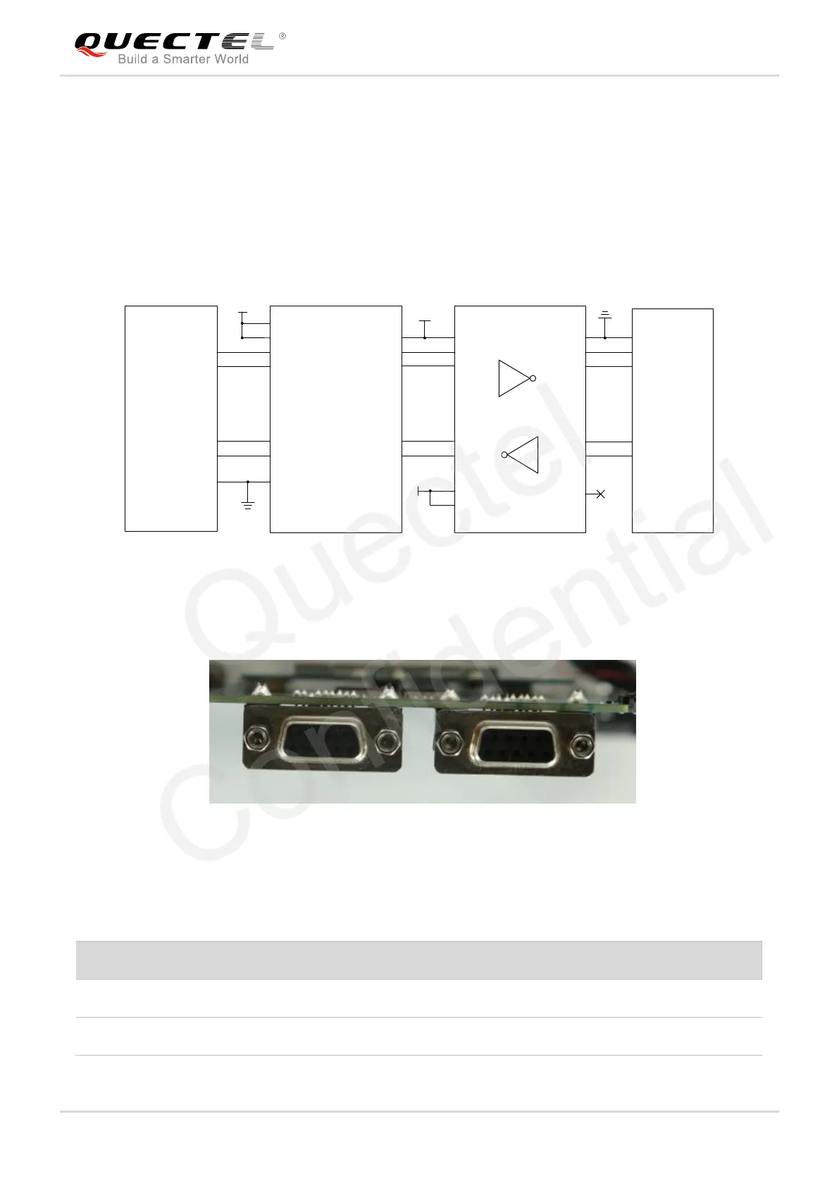
The following figure shows the block diagram of UART on Smart EVB G2.
TXS0104 EPWR
RXD_3.3V
CTS_3.3V
TXD_3.3V
RXD_1.8V
CTS_1.8V
VCCA
Module
GND
GND
1.8V
VCCB
3.3V
DIN 1
ROUT3
ROUT 2
ROUT 1
DIN4
DIN3
DIN 2
DIN 5
R1OUTB
FORCEON
/
3.3V
DOUT1
DOUT2
DOUT3
DOUT4
DOUT5
RIN3
RIN2
RIN1
VCC GND
OE
SN65C 3238
RTS
TXD
CTS
RXD
GND
RXD_3.3V
UART_TXD
UART_RTS
UART_RXD
UART_CTS
DB-9
/INVALID
FORCEOFF
TXD_1.8V
RTS_1.8V
Figure 35: RS232 Level Match Circuit
The following figure shows the pin assignments of main UART port (J1401).
Debug UART Main UART
2 3 5
7 8
Figure 36: Pin Assignments of Main UART Port
Table 10: Pin Definition of Main UART Port