UMTS/HSPA+ Standard Module Series
UC200T-GL Mini PCIe Hardware Design
UC200T-GL_Mini_PCIe_Hardware_Design 24 / 51
Special attention should be paid to the selection of ESD device on the USB data line. Its parasitic
capacitance should not exceed 2pF and should be placed as close as possible to the USB interface.
3.8. (U)SIM Interface
UC200T-GL Mini PCIe’s (U)SIM interface circuitry meets ETSI and IMT-2000 requirements. Both 1.8V
and 3.0V (U)SIM cards are supported. The following table shows the pin definition of the (U)SIM interface.
Table 9: Pin Definition of (U)SIM Interface
UC200T-GL Mini PCIe supports (U)SIM card hot-plug via the USIM_PRESENCE pin. The function
supports low level and high level detections. By default, It is disabled, and can be configured via
AT+QSIMDET command. Please refer to document [2] for details about the command.
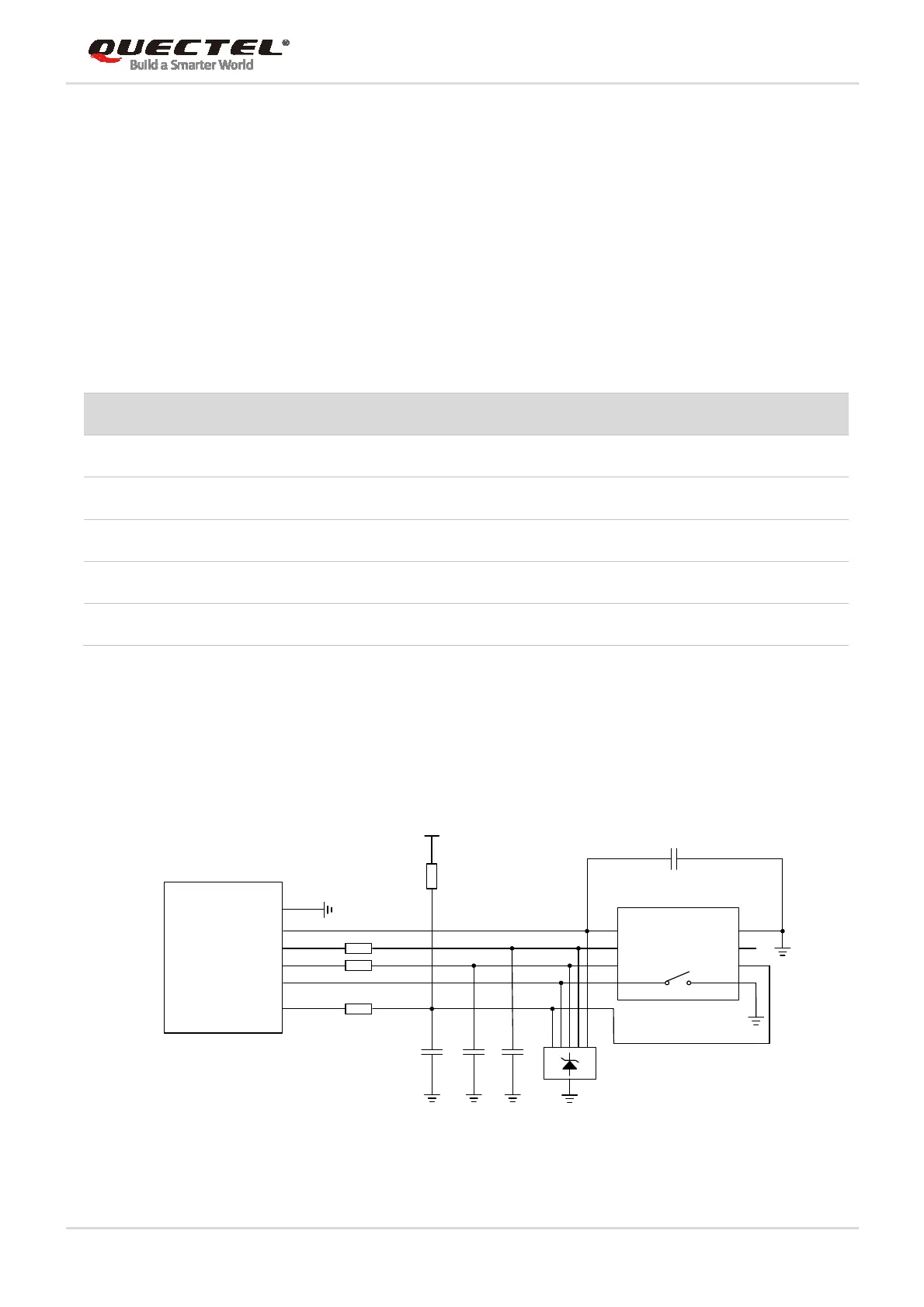
The following figure shows a reference design for (U)SIM interface with an 8-pin (U)SIM card connector.
USIM_VDD
GND
USIM_RST
USIM_CLK
USIM_DATA
USIM_PRESENCE
100nF
GND
GND
33pF 33pF 33pF
VCC
RST
CLK
IO
VPP
GND
GND
USIM_VDD
15K
(U)SIM Card Connector
Module
0R
0R
0R
Figure 6: Reference Circuit of (U)SIM Interface with an 8-pin (U)SIM Card Connector
Pin Name Pin No. I/O Power Domain Description
USIM_VDD 8 PO 1.8V/3.0V Power supply for (U)SIM card
USIM_DATA 10 IO 1.8V/3.0V Data signal of (U)SIM card
USIM_CLK 12 DO 1.8V/3.0V Clock signal of (U)SIM card
USIM_RST 14 DO 1.8V/3.0V Reset signal of (U)SIM card
USIM_PRESENCE 44 DI 1.8V (U)SIM card insertion detection
 Loading...


