UMTS/HSPA+ Standard Module Series
UC200T-GL Mini PCIe Hardware Design
UC200T-GL_Mini_PCIe_Hardware_Design 29 / 51
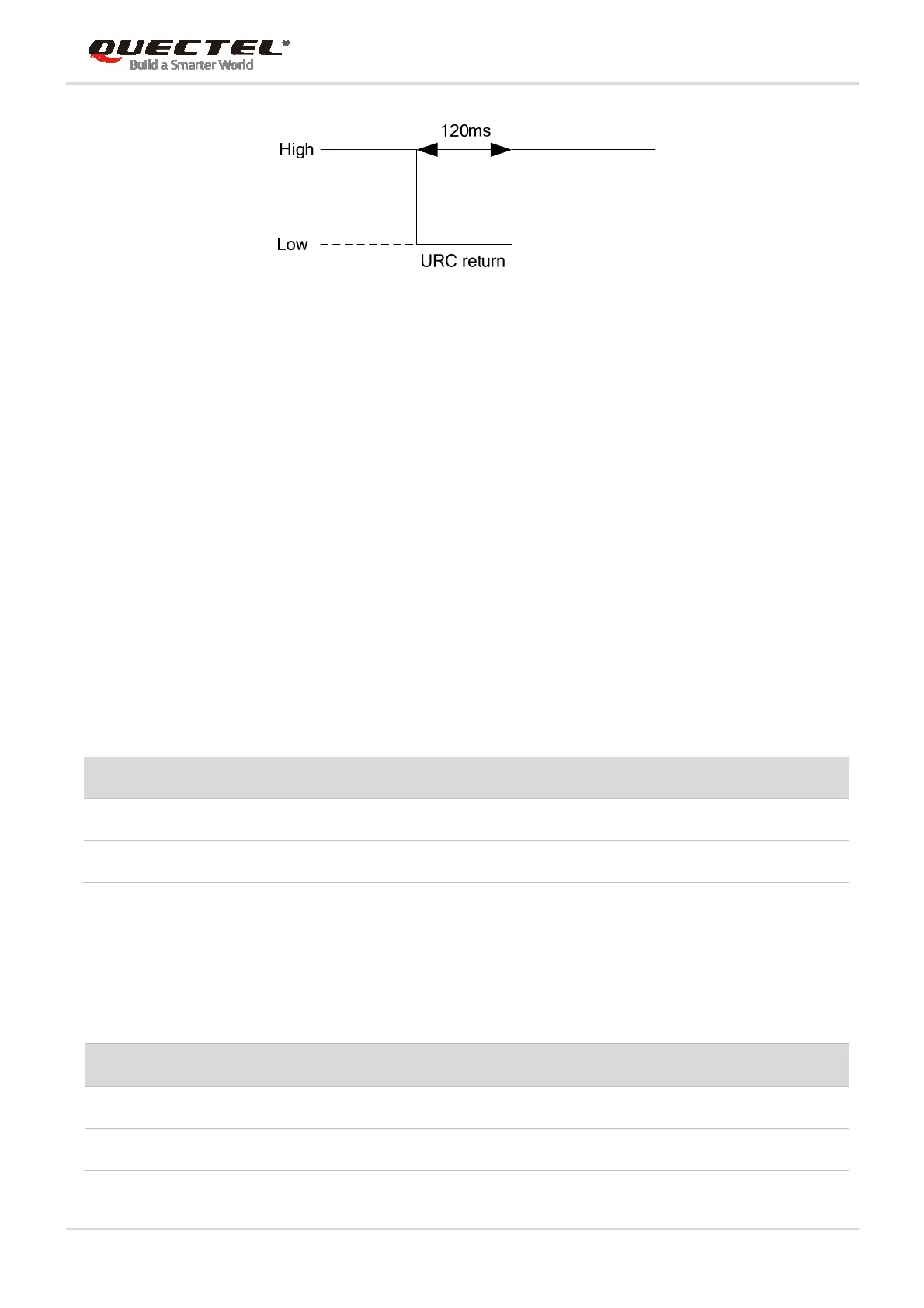
Figure 11: RI Behaviors
3.10.2. DTR Signal
The DTR signal is used for sleep mode control. It is pulled up by default. When module is in sleep mode,
driving it to low level can wake up the module. For more details about the preconditions for module to
enter sleep mode, please refer to Chapter 3.4.1.
3.10.3. W_DISABLE# Signal
UC200T-GL Mini PCIe provides a W_DISABLE# signal to disable or enable the RF function (GNSS not
included). The W_DISABLE# pin is pulled up by default. Its control function for airplane mode is disabled
by default, and AT+QCFG=“airplanecontrol”,1 can be used to enable the function. Driving it to low level
can make the module enter airplane mode.
Table 12: Airplane Mode Controlled by Hardware Method
Software method can be controlled by AT+CFUN, and has the same effect with W_DISABLE# signal
function, the details are as follows.
Table 13: Airplane Mode Controlled by Software Method
W_DISABLE# RF Function Status Module Operation Mode
High level RF enabled Normal mode
Low level RF disabled Airplane mode
AT+CFUN=? RF Function Status Module Operation Mode
0 RF and (U)SIM disabled Minimum functionality mode
1 RF enabled Normal mode
 Loading...


