UMTS/HSPA+ Standard Module Series
UC200T-GL Mini PCIe Hardware Design
UC200T-GL_Mini_PCIe_Hardware_Design 28 / 51
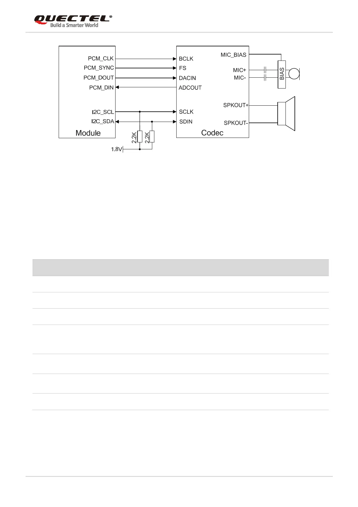
Figure 10: Reference Circuit of PCM Application with Audio Codec
3.10. Control and Indication Signals
The following table shows the pin definition of control and indication signals.
Table 11: Pin Definition of Control and Indication Signals
3.10.1. RI Signal
The RI signal can be used to wake up the host. When a URC returns, there will be the following behaviors
on the RI pin after executing AT+QCFG="risignaltype","physical".
Pin Name Pin No. I/O Power Domain Description
RI 17 DO 3.3V Output signal used to wake up the host.
DTR 31 DI 3.3V Sleep mode control.
DCD 33 DO 3.3V Data carrier detection
W_DISABLE# 20 DI 3.3V
Airplane mode control.
Pulled up by default.
Active low.
PERST# 22 DI 3.3V
Fundamental reset signal.
Active low.
LED_WWAN# 42 OC
LED signal for indicating the network
status of the module.
WAKE# 1 OC
Output signal used to wake up the host.
 Loading...


