UMTS/HSPA+ Standard Module Series
UC200T-GL Mini PCIe Hardware Design
UC200T-GL_Mini_PCIe_Hardware_Design 27 / 51
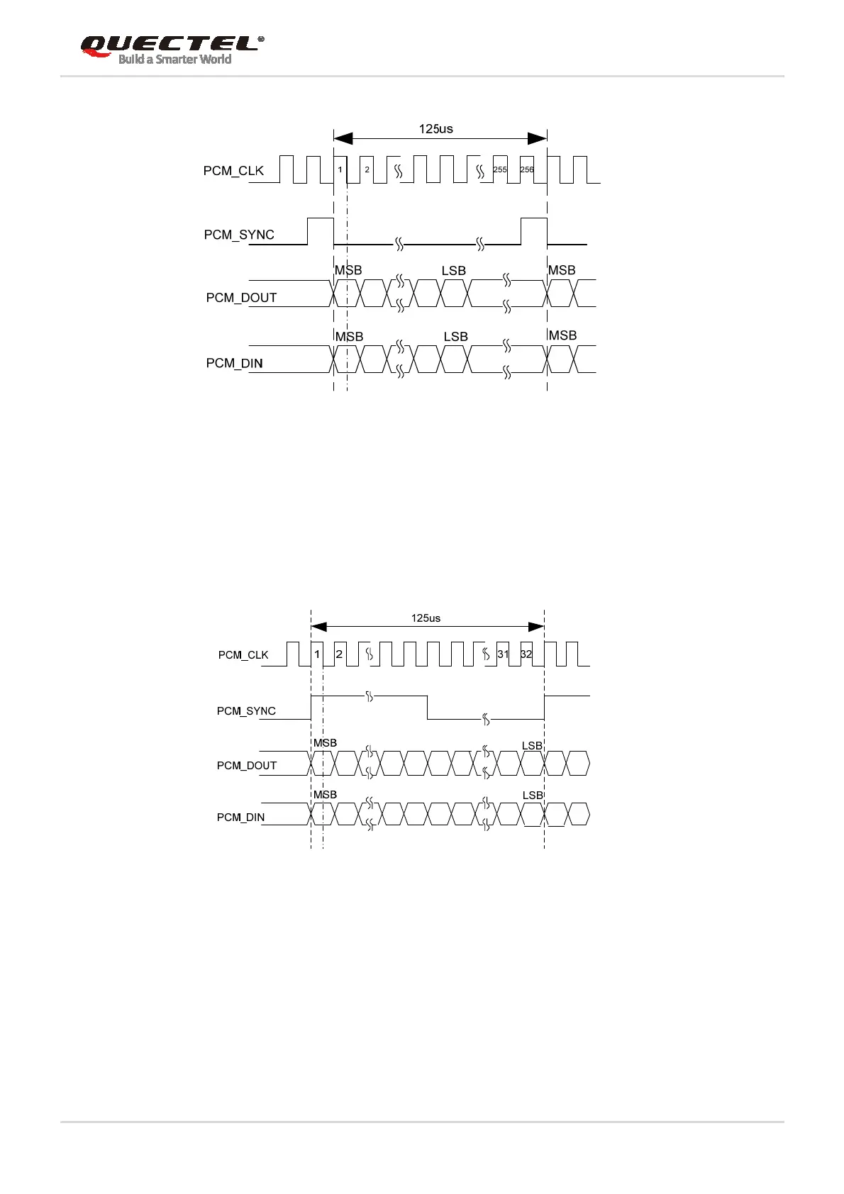
Figure 8: Timing in Primary Mode
In auxiliary mode, the data is sampled on the falling edge of the PCM_CLK and transmitted on the rising
edge. The PCM_SYNC rising edge represents the MSB. In this mode, the PCM interface operates with a
256kHz, 512kHz, 1024kHz or 2048kHz PCM_CLK and an 8kHz, 50% duty cycle PCM_SYNC. The
following figure shows the timing relationship in auxiliary mode with 8kHz PCM_SYNC and 256kHz
PCM_CLK.
Figure 9: Timing in Auxiliary Mode
Clock and mode can be configured by AT command, and the default configuration is master mode using
short frame synchronization format with 2048kHz PCM_CLK and 8kHz PCM_SYNC. In addition,
UC200T-GL Mini PCIe’s firmware has integrated the configuration on some PCM codec’s application with
I2C interface. Please refer to document [2] for details about AT+QDAI command.
The following figure shows a reference design of PCM interface with an external codec IC.
 Loading...


