39
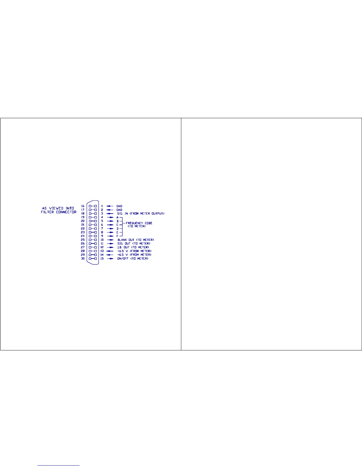
Figure 26. OB-300 External Filter Connector (Located on Top of
Filter)
MODE Switch
Selects either the 1/3 octave filter set (33 frequencies) or the 1/1
octave filter set (11 frequencies).
TIME
A screwdriver adjustment to control the automatic cycle time of each
filter frequency from approximately 5 to 30 seconds.
B. Filter Connector
The 30 pin connector on the top of the filter is used for connecting the
filter to the sound level meter. Figure 26 shows the pinout for the filter
connector.
XIV.
GENERAL
OPERATING
PROCEDURE
The Model
1800-300
Octave
Band
Analyzer
is made up
of the
Model 1800
Precision
Impulse
Integratin
g Sound
Level
Meter and
the OB-300
1/3 - 1/1
Octave
Filter
Set. The
two units
are connected together with the long captive screw provided with the filter.
The General Operating Considerations for the Model 1800 are basically the
same when using the Model OB-300 with the meter.
40
A. Operational Check
The Model 1800 should be calibrated as outlined in Section III of the meter
section (Checking the Meter Integrity, B. Calibration) while the OB-300 is
OFF. The OB-300 has a fixed input to output voltage ratio of approximately
1 (0 dB) at each center frequency and requires no adjustment. After the
meter is calibrated, check the filter for proper operation as follows:
1. Read the calibrator 1 kHz output level. Set the meter dB RANGE
switch so that the calibrator level will indicate within the upper
20 dB of the meter display. Set the RESPONSE switch to FAST,
WEIGHTING switch to LIN and MODE switch to SPL. Turn the POWER
switch to ON.
2. Set the OB-300 POWER switch to MANUAL and the MODE switch to 1/1.
Press the RUN button to place the meter into the RUN mode. Then
use the two direction buttons to select the 1 kHz filter.
3. Place the calibrator (and adapter if needed) onto the microphone.
Turn the calibrator ON. A meter reading that is very close to the
level listed on the calibrator should result. An error of +/- 0.5
dB is acceptable. This is due to the center frequency filter
tolerance of +/- 0.5 dB maximum.
4. Change the OB-300 filter frequency first to 500 and read the
display. Then change to 2k and read the display. At both
frequencies the readings should be 19 to 23 dB less than the 1 kHz
calibrator level.
5. Change the OB-300 filter frequency to 1k and the meter dB RANGE so
that the meter reads 20 to 40 dB less than full scale. Press and
hold the -20 dB button on the OB-100. The meter reading shall rise
approximately 20 dB to verify that the -20 dB button functions.
6. Remove the calibrator. The analyzer is now ready to use.
B. Taking a Measurement
1. Turn the meter POWER switch ON. The meter will come on in the
Pause mode. Perform a BATTERY test to verify that the analyzer has
sufficient battery power. Replace the batteries if the bar
indicator falls below the indicating arrow (located at 5 on the 0
- 60 scale).
2. Set the dB RANGE switch to 80 - 140 dB. Set the RESPONSE switch to
FAST, WEIGHTING switch to LIN (see note), and the MODE switch to
SPL.