7
Figure 2. Output Jack Connections
D. Output Jacks
All output jacks use a 3.5 mm stereo
plug. (See Figure 2) The following
describes each output function:
PRINT - Pressing the PRINT button
causes serial ASCII data
to be transmitted from the
print jack at appropriate
RS-232 levels. This data
may be sent to a serial
printer or a computer.
The baud rate is
determined by two switches
located in the battery
compartment. (See Figure
4, Battery Compartment
Internal Switches, for
switch settings).
DC - The Sound Pressure Level (SPL) over the 60 dB range selected is
linearly represented by a 0 to 1 volt DC output. Zero volts is
equal to the bottom of the range and 1 volt is equal to full scale.
This output is primarily provided for connecting to a 0 to 1 volt
input chart recorder or data acquisition device. (See IV. D.,
Chart Recording and Figure 8, Chart Recording of SPL)
AC - This jack furnishes an amplified SPL, (either weighted or
unweighted), depending on the WEIGHTING switch setting. The full
span of 60 dB is represented between 3.16 millivolts and 3.16 volts
RMS.
DATA - When the Model 1800 is in the RUN mode, an SPL reading will be
serially transmitted through the DATA jack at a rate of 16 times
per second. To make use of this function, the meter range switch
must be set in one of its two highest positions.
The data is an 8-bit signal proportional to the integrated sound
level for the last 1/16 second. The signal is normally at +6.5
volts. If the meter is in the RUN mode, data is sent as in Figure
3. Signal description is as follows:
8
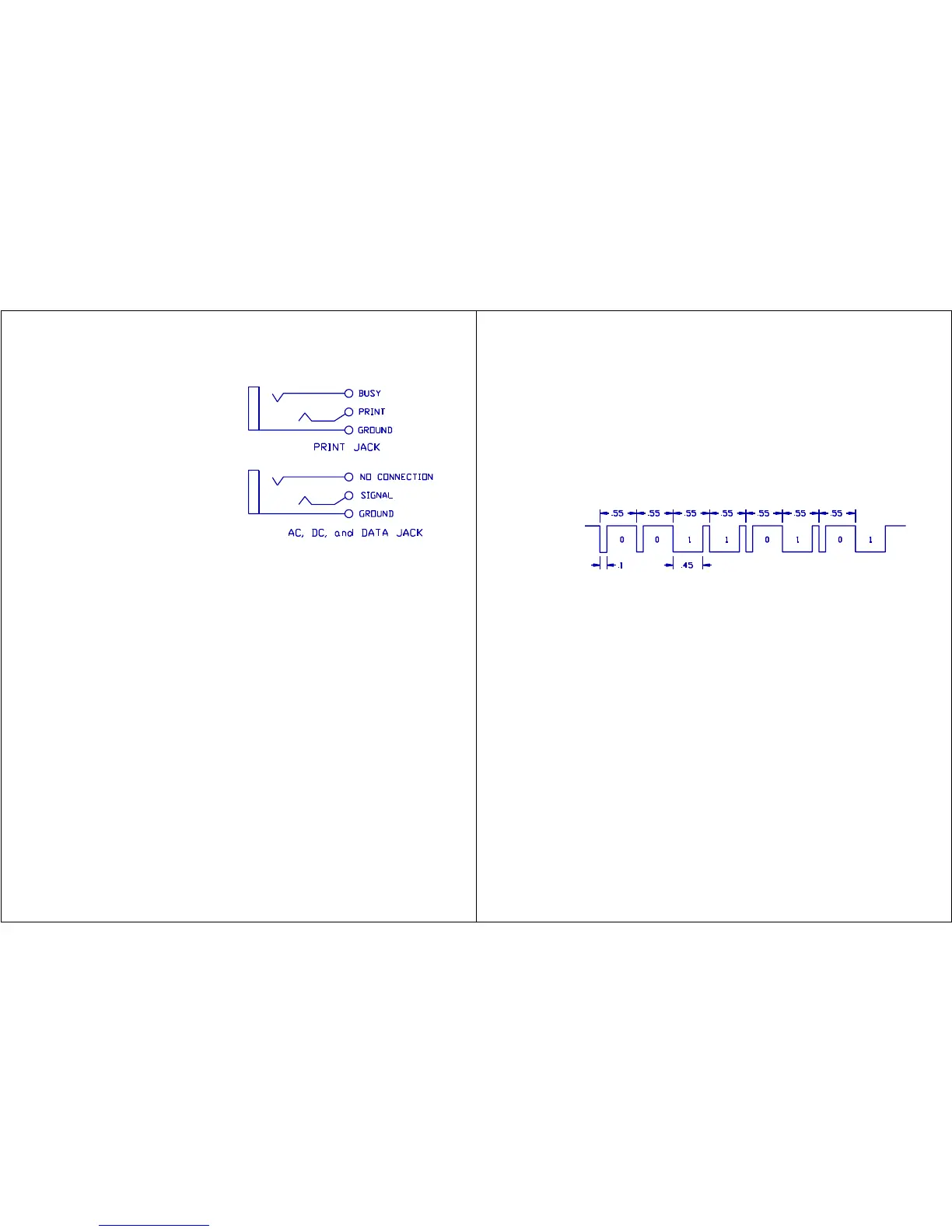
Figure 3. Data Jack Format
The signal goes to -6.5 volts every 0.55 msec.
If the bit is a 0 it will return to plus after 0.1 msec.
If the bit is a 1 it will return plus after 0.45 msec.
The signal is sent least significant bit first.
The resolution is 3/8 dB.
All 0's = 30 dB if the meter is set to the 60 - 120 dB range.
50 dB if the meter is set to the 80 - 140 dB range.
All 1's = 30 dB + 95.6 dB when set to the 60 - 120 dB range.
50 dB + 95.6 dB when set to the 80 - 140 dB range.
The example shown in Figure 3 is 10101100 binary = 172 decimal.
The level is (172 x 3/8) + 50 = 114.5 dB when on the 80 - 140 dB range.
E.
External
Filter
Connector
The 30 pin
connector
on the
bottom of
the meter
is used
for
connecting either the Model OB-300 combination 1/3 - 1/1 Octave Filter Set or
the OB-100 Octave Filter Set. Refer to section XIII for details regarding
this connector.
F. Internal Switches
There is an internal switch located in the battery compartment that is
accessible to the user. (Refer to Figure 4.)
Mic. Polarization - The small ON/OFF switch on the right-hand side operates
the 200 volt microphone polarization which is necessary
for condenser-type microphones.
Baud Rate - Actuators 1 and 2 of the dip switch, located through the
hole in the lower left, control the baud rate at which
the meter transmits data to a printer. Baud rates
available are 300, 600, 1200, and 2400.