10
CHC1102M GB F - REV005B
GB
S
E
N
S
O
R
C
A
N
H
U
P
DOWN
CAN L
S
E
N
S
O
R
C
A
N
H
U
P
DOWN
CAN L
150
150
000 M/M
UP ALARM
SPEED
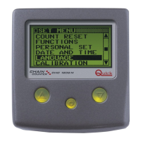
Connecting the instrument
After installing the socket as instructed above, proceed as directed below:
• Turn the cover's ring nut counter-clockwise and take it out.
• Insert the instrument's plug into the socket, being careful to plug it in the right direction.
• Turn the plug's ring nut clockwise until it is fully tightened.
Disconnecting the instrument
• Turn the plug's ring nut counter-clockwise and take it out.
• Cover the socket with the cover provided, turning the ring nut clockwise
ATTENTION: make certain the socket is covered with the cover provided when the instrument is
disconnected.
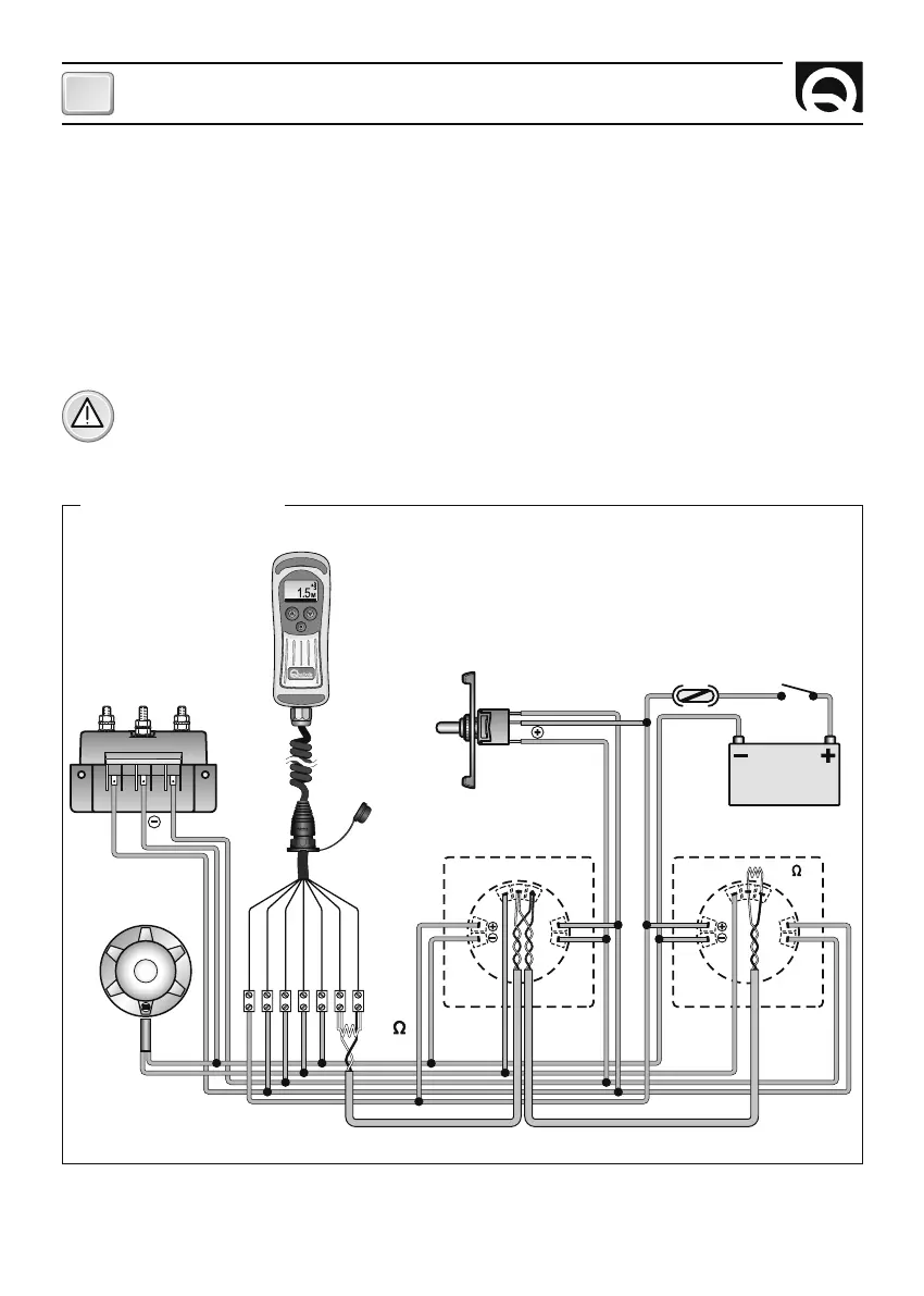
THE WIRING DIAGRAM
SWITCH
FUSE
4A FAST
GYPSY
SENSOR
CONTACTOR UNIT/
REVERSING CONTACTOR UNIT
AUXILIARY
COMMAND
BATTERY
12/24 V
BROWN
BLEU
BLACK
WHITE
GREEN
RED
GREY
UP
DOWN
UP DOWN
INSTALLATION
CHC 1102 M CHC 1102 M