3.3 SV3022 Solenoid Valve
1. Connect the pipework to the inlet/outlet of the valve (Refer to illustration). We
recommend the use of compression/union type ttings (not supplied) to ease
removal of the valve if required.
2. Unscrew the electrical connector retaining screw and remove the electrical
connector. Remove the retaining screw from the connector.
3. Lever the insert out of the electrical connector using a small screwdriver.
4. Fit the electrical wiring through the cable gland and connect it to the terminals
in the insert. Wiring polarity is not important.
5. Reassemble the electrical connector and ret it to the solenoid coil. Tighten
the retaining screw.
6. The SV3022 Solenoid Valve is tted with a high power coil. A maximum of ve
SV3022 Solenoid Valves may be connected to one Rada Pulse Control Box.
Important! These must be connected to alternate outputs of the Rada Pulse
Control Box (e.g. 1, 3, 5, 7, 9).
Each fuse in the Rada Pulse Control Box supplies a single pair of outputs (e.g.
Fuse 1 = Valve 1 / Valve 2, Fuse 2 = Valve 3 / Valve 4).
Do not connect multiple SV3022 Solenoid Valves to any one fuse.
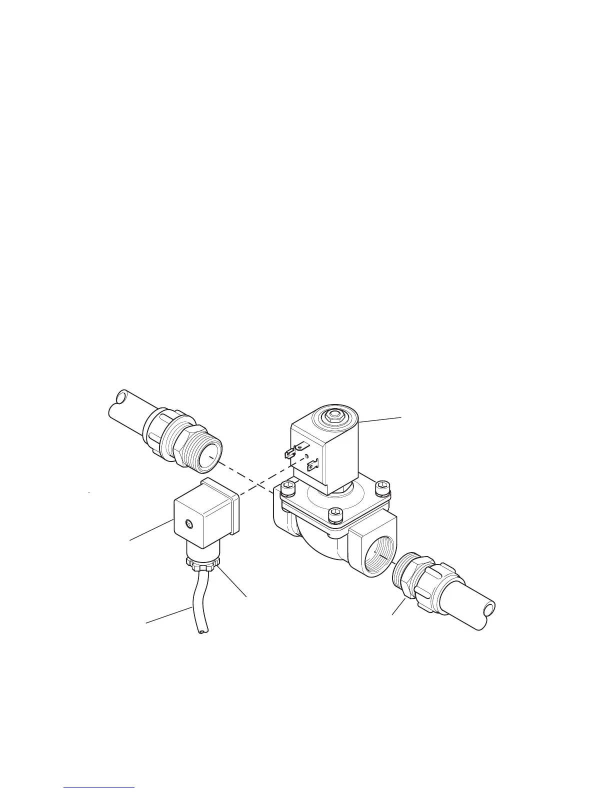
Installation of SV3022 Solenoid Valve
Electrical
Connector
Solenoid Coil
Cable Gland
Electrical Wiring
Compression/Union
Type Fitting