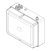
1. Install the Control Box
The Control Box is intended for wall-mounting to a suitable at dry surface using
the supplied xing screws and sealing washers. The control box must be accessible
for maintenance. If the wall is uneven it is advisable to provide a at mounting
board / frame so that the control box does not become distorted.
Control Box Electrical Supply
This appliance is intended for permanent connection to the xed electrical wiring
of the mains electric system via a double pole switched connection unit fused at
3 amps, which has at least 3 mm contact separation.
A mains 230 V supply cable of 2 metre length is pre-connected to the control box,
this must not be removed; do not renew the cable inside the box if damaged.
The system low-voltage 12 V AC output is fuse-protected. This appliance is IP54
protected when blanking caps are tted to unused cable holes, and the cover and
seal is tted correctly.
All mains cable used on the installation must be HAR approved (0.75 mm
2
).
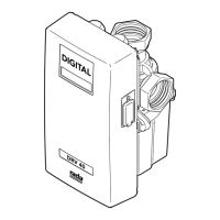
Control Auxiliaries
The control PCB has terminals to allow control of auxiliary items by the Rada Pulse
system (e.g. pump, fan, lights and disinfection).
Important! Do not connect mains voltage to the PCB Auxilliary Terminals.
These connections are designed to switch mains voltage loads through contacts of
a 12 V DC relay (max coil resistance 160 ohms).
A relay box designed for use with the Pulse Control Box is available, refer to section:
'Description, Accessories'.
Programming of all outlets is via the hand held programmer, refer to section:
'Description, Accessories').
1. Use the installation template (supplied) to mark the positions of the xing holes
for the control box.
2. For solid walls, drill and plug the xing holes. For other types of wall structure
alternative xings (not supplied) may be required.
3. Remove the cover from the control box (Refer to illustration).
4. Hold the control box in position and secure with the xing screws (supplied).
Note! Make sure that you t the sealing washers to the control box xing
screws.
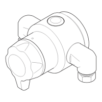
5. Install the Rada Pulse Sensors and Solenoids, refer to sections: 'Installation,
Install the Sensors' and 'Installation, Install the Solenoids'.
Note! Inside the cover of the control box is an information label for completion
by the installer. The information on this label should identify the position in the
building of individual sensors and solenoids (refer to example on label).
6. Fit the cover to the control box and secure the cover screws (6 off).
Note! Make sure that seal is tted correctly.
 Loading...