2. Install the Sensors
General
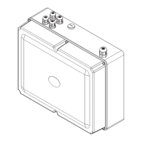
The Rada Pulse Sensors use the 12 V AC electrical supply provided by the
transformer within the Rada Pulse system control box.
Sensors should be tted in a dry position, allowing access for adjustment or
maintenance.
The sensors should be positioned a minimum of 0.5 m away from any heat source
to prevent false operation.
Make sure that the area is adequately ventilated. Steam or condensation may
affect the sensitivity and operating life of the sensor.
Always make sure that the sensors ‘view’ is not obstructed.
Do not install the sensor opposite a mirror or reective surface.
Use conduit when installing cables through the wall.
It is recommended that low voltage system cables are installed within conduit or
trunking to provide mechanical protection for the cables and to allow removal or
maintenance of system components. Do not bury system cables directly into the
wall surface.
Note! Do not join sensor cables in close proximity to the sensor as this can allow
water ingress and impair the function of the Rada Pulse System.
Note! If a system cable requires lengthening use only the 3M
TM
connectors (packed
with Pulse sensors and the Rada Pulse cable extension accessory kit). 3M
TM
cable
connectors must be positioned within a dry area to prevent water ingress affecting
the operation of the Rada Pulse system.
When installing sensors in an existing pretiled area the system cable should be
installed within surface mounted conduit or trunking. Do not bury system cables
directly into the wall surface.
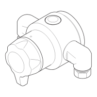
Note! Do not install Solenoid Valves directly above conduit or trunking.
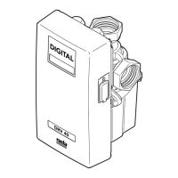
2.1 Rada Pulse 120 and 122 Sensors
1. Remove the grub screw and cover from the sensor.
2. Mark, drill and plug the wall for two securing screws (supplied). Make sure the
holes are lined horizontally, and the xing is preferably in the centre of a at tile.
Alternative xings (not supplied) may be necessary for some wall structures.
Note! If the sensor bridges a groove between two tiles, we recommend this
gap be lled with silicone sealant.
 Loading...