True to the Music
Radial Engineering Ltd. SW8-USB™ Owner’s Manual
4
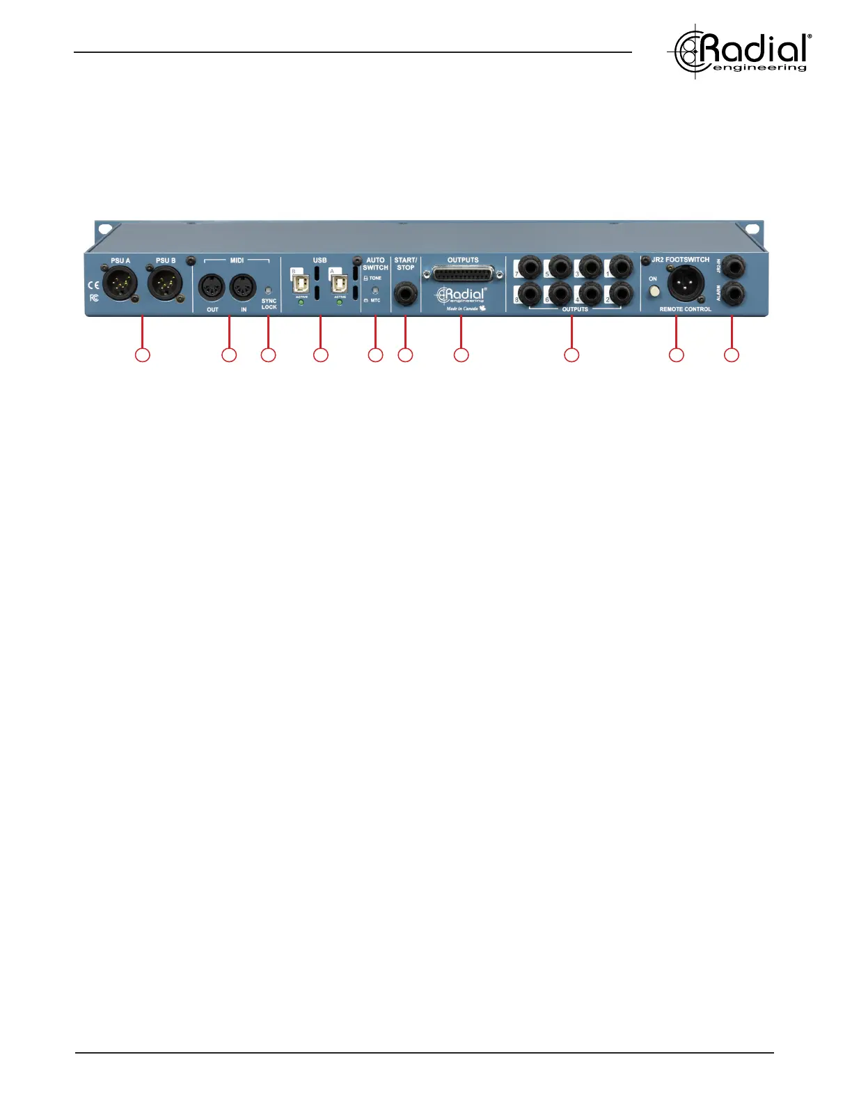
REAR PANEL FEATURES
12 13 14 15 16 17 18 19 20 21
12. PSU A & B INPUTS: Connections for locking 4-pin power supplies (included). The PSUs for the SW8-USB are switching
supplies to allow for easy international usage.
13. MIDI IN/OUT: Allow you to to pass MIDI signal to and from the computer on the active USB connection. When SYNC LOCK is
disengaged, signal sent to the MIDI IN feeds both the primary and backup computers at once, allowing you to use an external MIDI
controller to trigger playback on both computers simultaneously.
14. SYNC LOCK: When engaged, this switch makes it possible to pass MIDI information from the primary computer to the backup
computer to allow for syncronized playback. Disengaging this switch allows an external MIDI controller or a footswich connected to
the START/STOP input to trigger playback on both computers simultaneously.
15. USB A & B: Type-B USB connections to directly connect your primary and backup playback computers for up to eight channels of
analog audio playback per SW8-USB. Compatible with Mac OS only, featuring 192kHz/24bit converters.
16. AUTO-SWITCH INPUT: Selects whether Tone via SPDIF or MTC is used for the auto-switch inputs of the SW8-USB. Tone (SPDIF)
should be used for the lowest latency when switching over to the B inputs.
17. START/STOP: 1/4” TRS connection allows you to send stop/start MMC signals to your computers to control and synchronize
playback. Can be used with standard contact closure footswitches such as the JR1-M remote footswitch.
18. DB25 OUTPUTS: Line-level outputs 1-8 over a DB25 multipin connection. These outputs are always active regardless of the
setting of the front panel MUTE switch, and they will follow the primary or backup computer along with the main XLR outputs.
19. 1/4” TRS OUTPUTS: Balanced output jacks are wired in parallel with the DB25 monitor outputs. These outputs operate at
line-level and will always be active regardless of the MUTE switch setting on the front panel.
20. JR-2 FOOTSWITCH INPUTS: XLR and 1/4” TRS connections allow the optional JR-2 remote footswitch to control the switching
and Standby functions of the SW8-USB. Standard 1/4” TS contact-closure footswitches and MIDI controllers with switching outputs
can also be used to select between the primary and backup computers.
21. ALARM: 1/4” TS connection from an internal relay can be used to turn on an external beacon when a dropout is detected at the
auto-switch input for computer A. This output can also be used to link multiple SW8-USB units together simultaneously.