28 QD134-15
7.5 CHANGING THE FRONT SPROCKET
1. In order to change the front sprocket, first remove the M8 countersunk bolt inside the nut on the
sprocket. (It is important to be careful when removing this bolt due to the thread containing Loctite; it is
recommended to heat up the area slightly in order to make removal easier.
2. Once this bolt has been removed, using a 36mm socket, the nut holding the front sprocket on can be
removed. The nut should also have Loctite applied for fitting.
3. The next step is to slide the front sprocket off of the shaft, this is likely to need a small amount of
prying away as Loctite will have been applied to the splines
4. Following removal of the sprocket, clean up the shaft and the splines before re-applying the Loctite
648 and activator all the way round the splines and threads.
5. When re-fitting the nut for the sprocket, the torque setting is 115 Ft/Lb. It is a good idea to re-check
the alignment at this stage as a general maintenance tip.
6. The final step is to re-fit the M8 countersunk bolt; this is to be torqued to 25 Ft/Lb along with having
Loctite 648 and activator applied prior to insertion.
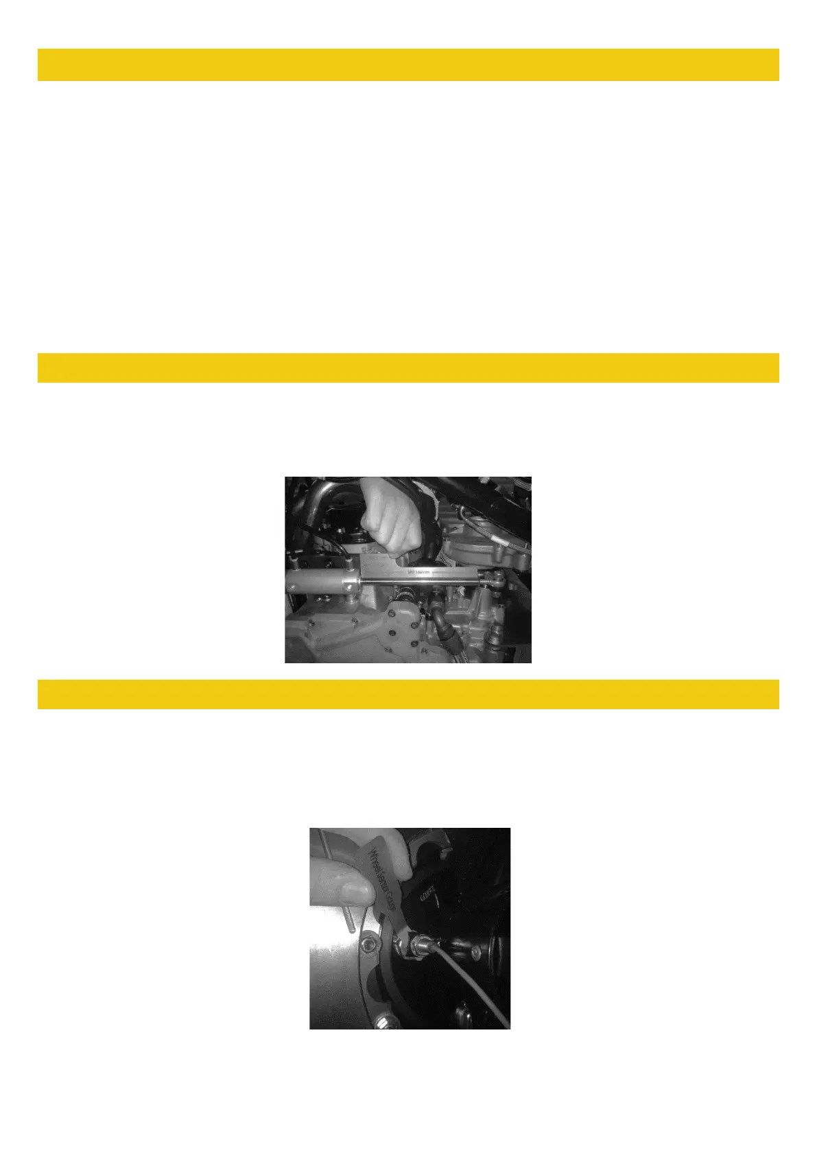
7.6 GEARSHIFT ACTUATOR SETUP
The actuator is a key part in changing gear in the SR1, if the actuator is incorrectly adjusted it can cause
gear shift issues, and has the potential to damage the internals of your gearbox. Use the jig (AT0033) for
setting the Actuator length on the SR1, the total length from the casing to the nut should be 166mm. This is
simply done as shown in the picture below: You should regularly check for excessive play in both bearings.
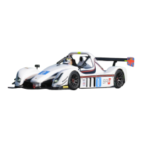
7.7 WHEEL SPEED SENSOR SETUP
Use the jig for setting the wheel speed sensor (AT0042). Using a pair of 13mm spanners, set the wheel
speed sensor no closer to the pickup point than the thickness of the Wheel Sensor Gauge (2mm). The pickup
point is the end of the brake disc bolts on an SR1. When fitted, check the sensor is working by ensuring it is
plugged in, then turn the power on and spin the disc, the sensor should light up when it sees each disc bolt,
be sure to check the gap on all bolts. This is shown in the image below: