The composite
sync
data is sourced from Z5, pin
8,
and is
applied to the base
of
transistor
Q2.
Each time the
base of
Q2
goes
about
0.6
volts below 5 volts, Q2
turns on, which
applies
5
volts to resistor R28. (Actually,
the voltage
applied
to
R28 will be less than
5.0
volts,
due to the satura-
tion voltage
of Q2.)
SYNC
The dot data from
Z30, pin
1,
is inverted by Z41,
pins 6
and 7.
The resulting output
at pin 5
is
a normally low signal
which goes high only when the shift registers output
a dot.
Z41
is a high current
driver. The
output at pin 5 is the col-
lector of
the
output buffer transistors.
So,
essentially,
we
have the video and
sync
going to two transistors. These
transistors act as switches
controlling
current flow through
resistor
network R28, R27 and R23.
Figure
9A
shows a
simplified
drawing of the circuit.
Q2
and Z41 are represented as switches. When
Q2 is
"open-
ed", there is no
voltage applied
to
R28; and the output
node is at ground
level.
When
Q2 "closes" and with
Z41
also
held "closed", the output
voltage
goes
up to about
1.23
volts. This voltage will be called "the
black level".
Voltage below this
level is "blacker-than-black" and is
known as sync level. Voltage above 1.23
volts can be
called the "white
level". Normally, the black level stays at
1.23 until the
sync at Z5, pin
8,
goes high, turning off
Q2,
forcing the output at
the node to
go
to ground. When dot
data causes
switch Z41
to
open, the voltage at the output
node
increases to
about
2.75
volts.
We now have a
signal at the output node that contains both
video dots and sync information.
This
signal is
almost ready
for the display.
All that is necessary at this point is a
little
level shifting and
output buffering.
R28
270
I
-*-
OUTPUT
R
23
120
R27
330
Figure
9A.
Simplified Video
Mixing
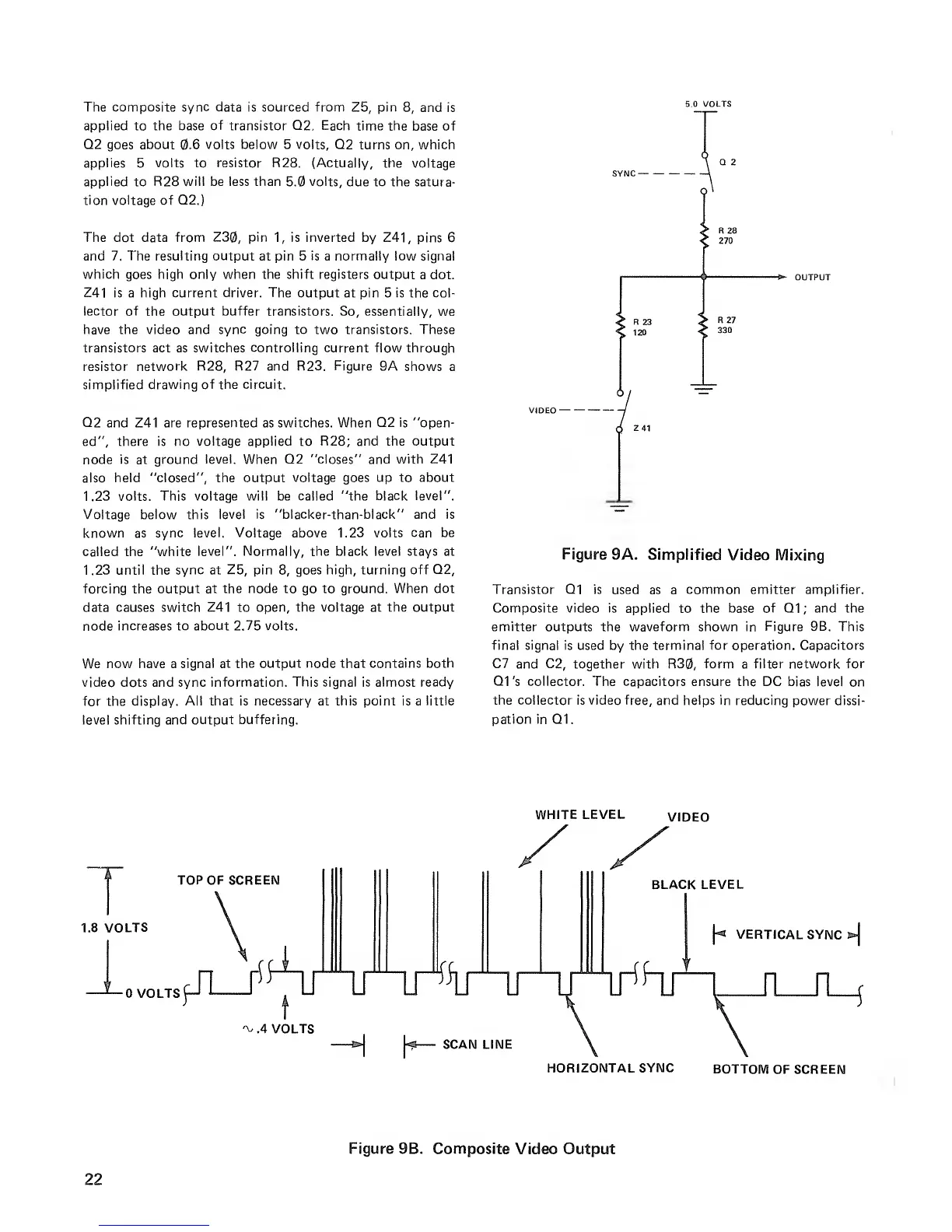
Transistor Q1 is used
as a
common emitter amplifier.
Composite video is applied
to
the base of
Q1
;
and the
emitter outputs the waveform shown in
Figure 9B.
This
final signal is used by the terminal for operation. Capacitors
C7
and
C2,
together with R30, form a
filter
network
for
Q1's collector. The capacitors ensure the DC bias
level on
the collector is video free,
and
helps in
reducing power dissi-
pation in Q1.
1.8 VOLTS
WHITE LEVEL
VIDEO
TOP OF SCREEN
BLACK
LEVEL
-0
VOLTS
\**
VERTICAL
SYNC
*\
n
n_t
'v
.4 VOLTS
»»j
|«p
—
SCAN LINE
HORIZONTAL
SYNC
BOTTOM
OF SCREEN
Figure 9B. Composite
Video Output
22
 Loading...


