will be generated. One millisecond later, the
start pulse of a
new bit is generated. If this bit is to be a zero, then
there
will
be a two
millisecond delay before
another pulse is
generated; and this pulse starts the third bit 'time. The
pulses
are
outputted to the cassette recorder
from pin 5 of
J3. This pin is tied to the
AUX
input of the recorder. The
CPU outputs all of the instructions
in system
RAM
to tape
during the
CSAVE function.
When the function is
complete, audio to the recorder is disabled and a low is
outputted at D2, shutting off the recorder's motor.
Data
is written on the tape in
the following format:
Upon
CSAVE,
the
CPU
forces Z59
to output 128 zero
bits. It
then outputs hex code A5 used
by the CPU
during CLOAD
for synchronization. A
two byte starting
address and a
two
byte ending
address is added next. Then
the data follows,
however
long it is. After the
data, the last portion
to be
stored on tape is the check
sum. This
one
byte
number is
the
sum
of all data added together. It
is used by
the
CPU
to ensure what it CLOADed-in
is what was CSAVEd-out.
If the check sums
don't
match
up, then
there was a load
error.
in. Matter
of fact, the recorder adds stuff to the signal.
Motor
noise and
60
cycle hum complicate
signal pro-
cessing
considerably.
Upon a CLOAD instruction from
the
CPU,
the
recorder
motor turns
on and
cassette audio
is applied to
pin 4 of J3.
This signal called CASSIN, is
tied to capacitor
C24 and
resistor R67
at the input of the audio processor
section. Z4,
pins
1,
6 and
the
output pin
5,
form an active
filter. This
part of the circuit is used to filter out undesired
noise and
hum from CASSIN. It
is a high pass filter,
with about a 2
KHz
roll off.
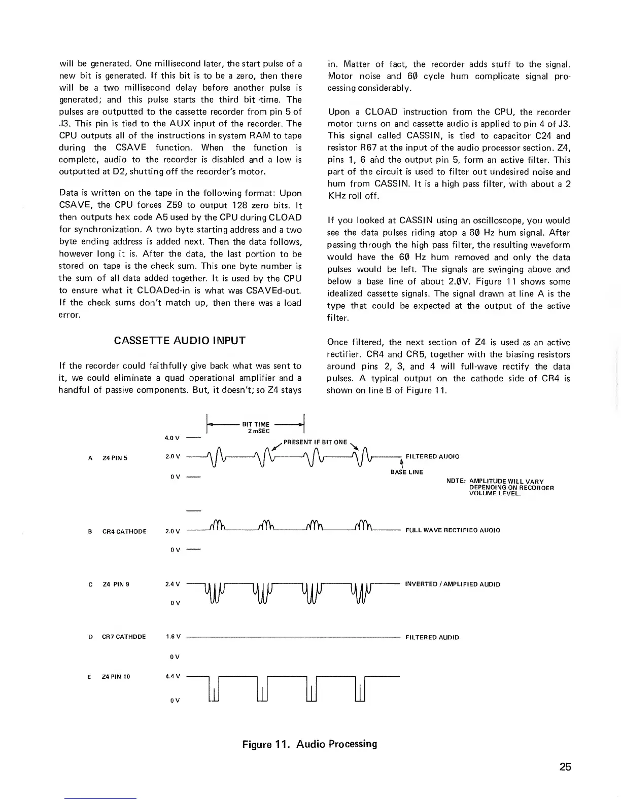
If you looked
at
CASSIN
using an oscilloscope, you would
see the data pulses riding
atop a 60
Hz
hum
signal. After
passing through
the high pass filter, the resulting waveform
would
have the 60
Hz
hum removed and only
the data
pulses would be left. The signals
are
swinging above
and
below
a base line of about 2.0V. Figure
1 1 shows some
idealized
cassette signals. The signal
drawn at line A is the
type that could
be expected at the output of the active
filter.
CASSETTE AUDIO INPUT
If
the
recorder could faithfully give back
what was sent to
it, we could
eliminate
a quad operational amplifier and a
handful of passive components. But, it doesn't;
so
Z4
stays
Once filtered,
the next section of
Z4
is used
as
an active
rectifier. CR4
and
CR5,
together with the biasing resistors
around pins
2, 3,
and 4 will full-wave
rectify the data
pulses. A typical
output on the cathode side of CR4 is
shown on line B of Figure
1 1.
A Z4
PIN
5
4.0 V
2.0 V
V
•
BIT TIME
2mSEC
. PRESENT IF BIT ONE .
l/
A
X
—
\j\j
—
\jv
—
\f\j
—
\jV
FILTERED AUDIO
NOTE:
AMPLITUDE
WILL
VARY
DEPENDING
ON
RECORDER
VOLUME
LEVEL.
B
CR4 CATHODE
2.0
V
_M
HTh
rWr\
tfYk
FULL WAVE RECTIFIED AUDIO
C
Z4 PIN 9
2.4 V
V
~W^W
INVERTED
/AMPLIFIED
AUDIO
D CR7 CATHODE
1.6 V
FILTERED
AUDIO
E
Z4PIN10
w
LU
W W
Figure
11.
Audio
Processing
25
 Loading...


