The
CPU
looks
to
the ROM for
instructions. The CPU
then
follows the ROM's instructions
and looks to the keyboard,
then
the
RAM. In
all cases, the CPU
applies address loca-
tions
to the
ROM, RAM,
and keyboard. The
data lines are
then
checked for input data that
corresponds
to these
address locations.
In
case
of an output from
CPU
to
RAM,
the
CPU
selects the address,
puts data on the
data lines,
then instructs
the RAM to store
the data that is on the data
lines.
Notice
that
only the
CPU
communicates
with all
other
sections. If
the CPU
is told by ROM
to
store something
from
ROM into RAM,
the CPU
can't make
the RAM
receive ROM
data direct. Instead,
the CPU
takes the
data
from ROM
and then sends it
to RAM. The CPU
must
act as
intermediary between
the two. The
reason for this
is that
the
CPU
is the
only
section that
can address
locations
and
pass data to all other sections.
KEYBOARD, VIDEO
RAM,
VIDEO
PROCESSING
The
keyboard section is
not necessary
as far as the CPU
is
concerned,
but it is very necessary
for the
Operator. The
keyboard
is our method of
making known
our instructions
to the
CPU.
The opposite
is true for
the video RAM.
In this
case,
the
CPU
wants to tell us it
needs data
or it may
want
to
show us the result of
a
complex
calculation.
So, the
request
for more information
or the result
is stuffed into
the video RAM.
Anything in video
RAM is
automatically
displayed
on
the monitor.
The video
processing
section
handles this. Data in
the video RAM is in
ASCII.
Converting
ASCII
into the alphanumeric
symbols
we recognize
is the
job of the video processor.
A ROM
contains all
of the
dot
patterns. The ASCII locates
the character
pattern,
and the
video
processor sends it out to
the terminal.
VIDEO
DIVIDER
CHAIN
THE
MEMORY
MAP
Some customers call
the Factory
Customer
Service
Center
and
ask "Which
output
port
is
the display?"
These
cus-
tomers
are
told
that the TRS-80
does
not use
an output
port for
the display.
They are
told that
the TRS-80 is
memory-mapped. In
a memory-mapped
system an
address
will define
and select all
other subsections.
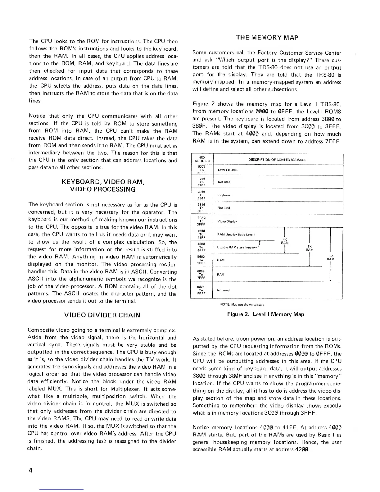
Figure
2 shows the memory
map for
a Level I TRS-80.
From
memory
locations
0000
to 0FFF,
the Level I ROMS
are
present. The
keyboard
is
located
from
address
3800 to
380F.
The video
display is located
from
3C00
to
3FFF.
The
RAMs start
at
4000 and, depending
on
how much
RAM
is in
the system, can
extend down
to address 7FFF.
HEX
ADDRESS
DESCRIPTION
OF CONTENTS/USAGE
0000
To
0FFF
Level 1 ROMS
1000
To
37FF
Not used
3800
To
380 F
Keyboard
3810
To
3BFF
Not
used
3C00
To
3FFF
Video Display
4000
To
41FF
I
RAM
Used by Basic Level
1
J
K
1
M
iK
VM
4200
To
4FFF
f
RAM
Useable RAM
starts here»—^
8
1
5000
To
5FFF
RAM
6000
To
7FFF
RAM
8000
To
FFFF
Not used
NOTE:
Mop not drawn
to scale
Figure
2. Level I Memory Map
Composite video
going to a terminal is
extremely complex.
Aside
from the video signal,
there is
the horizontal
and
vertical sync. These signals
must be very
stable
and be
outputted in the correct
sequence. The CPU
is busy
enough
as it
is, so the
video
divider chain
handles the TV
work. It
generates the sync signals
and addresses the
video RAM in
a
logical order
so
that
the video processor
can handle
video
data efficiently. Notice the
block under
the video RAM
labeled MUX.
This is short
for Multiplexer. It
acts
some-
what
like
a multipole, multiposition
switch.
When
the
video
divider chain is in control,
the MUX
is switched
so
that only addresses from the
divider chain
are directed
to
the video RAMS. The CPU
may need
to read or write
data
into the video RAM. If so, the
MUX is
switched
so that the
CPU
has control over video
RAM's
address. After
the
CPU
is finished,
the addressing task is
reassigned
to the divider
chain.
As stated before, upon power-on, an
address
location
is
out-
putted by the
CPU
requesting information from the ROMs.
Since the ROMs are located at addresses
0000
to
0FFF,
the
CPU
will be outputting addresses in this
area.
If
the
CPU
needs some
kind
of keyboard data,
it will output addresses
3800 through
380F
and see if anything
is
in
this "memory"
location. If
the
CPU
wants to show the programmer
some-
thing
on the
display, all it has
to do is address the video dis-
play
section of the map
and
store data
in these locations.
Something
to remember: the video display
shows
exactly
what is
in
memory locations 3C00 through 3FFF.
Notice
memory
locations
4000
to 41
FF.
At address
4000
RAM
starts. But, part of the RAMs are used by Basic I
as
general housekeeping memory locations. Hence, the user
accessible RAM
actually starts at address
4200.
 Loading...


