RD4000 Locating System User Manual
Page 69
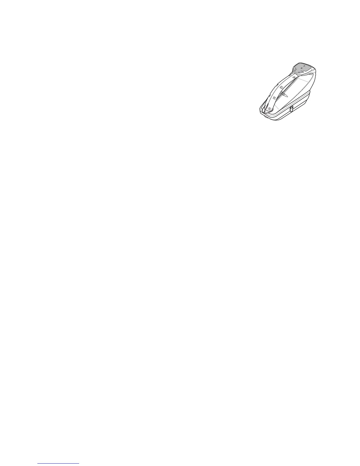
RD4000T3 and T3F Transmitters
Technical Specification
Description: RD4000 transmitter
Part No: 10/T3 –* (*=version)
10/T3F –* (*=version)
Physical:
Construction High Impact thermoplastic injection moulded case sealed to
IP55 (excludes all battery tray variants)
Ruggedness Withstands one metre drop onto concrete (BS EN 60068-2)
Dimensions Approximately 180mm/7.1”(D) x 350mm/13.78”(W) x 230mm/9” (H)
Weight Approximately 4.2kg/9.26Ib
Available Operating Modes:
Locate mode by Induction
Locate Mode by Direct Connection
FaultFind Mode by Direct Connection (T3F only)
Available Frequencies (±3Hz)
1 Induction Frequency from the following: 8.192kHz, 32.768kHz, 65.536kHz, 83.000kHz
or 200.000kHz – factory configurable
Up to 3 Direct Connection Frequencies from RD standard range 440Hz – 200kHz –
factory configurable
FaultFind Output (RD4000T3F Only)
FaultFind frequency 8.192kHz/8Hz composite signal compatible with existing
Radiodetection fault finding equipment
FaultFind Voltage 120V at 8mA maximum.
Audio Indication
Transmitter On 1 second tone at switch on
Connection Quality Sliding Tone from 40-400Hz lower tone equals more
current on line (i.e. better connection)
Low Battery Connection Tone pulses off 1 second in 5
Alarm Condition 2 second warning tone
Visual Indication
Nine LEDs provide feedback of transmitter operation
Output Level indicator Four Red LEDs
Induction selected One Red LED
Frequency/Mode selection Four Green LEDs
All nine LEDs illuminate for 2 seconds at switch on as a lamp check function
Output Protection
Output protected from inadvertent connection to 240V AC RMS.
F
F
F
F
4
4
0
H
z
4
4
0
H
z
3
2
k
H
z
3
2
k
H
z
6
5
kH
z
6
5
kH
z
8
kH
z
8
kH
z
RadiodetectionRadiodetection
RD4000T
3
RD4000T
3