RD8000 Operation Manual v
Table of figures
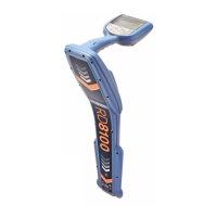
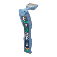
Figure 2.1: RD8000 receiver 2
Figure 2.2: RD8000 showing Bluetooth
®
antenna
2
Figure 2.3: receiver keypad 2
Figure 2.4: receiver LCD 2
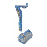
Figure 2.5 RD8000 transmitter 4
Figure 2.6: Rechargeable battery pack 4
Figure 2.7: transmitter keypad 4
Figure 2.8 transmitter LCD 4
Table 5.1: Bluetooth
®
error codes
15
Figure 7.1 Line tracing 19
Figures 7.2: Pinpointing a target line 19
Figures 7.3: Pinpointing with Peak/Null 19
Figure 8.1: Taking a depth reading 22
Figures 8.2: Depth readings 22
Figure 8.3: Current readings 24
Figures 8.4 – 8.6: Taking current readings 24
Figure 8.7: Current readings using transmitter
signals
25
Figures 9.1 – 9.4: Interference from services 26
Figure 9.5: Making double-ended connections 28
Figure 10.1: Connecting clamps 29
Figure 10.2: Standard clamp 30
Figures 10.3 – 10.4: Connecting transmitter
clamps
30
Figure 11.5 CD clamp 31
Figure 10.6: Sonde deployment 32
Figure 10.7: Locating a sonde 32
Figure 10.8: Calculating sonde depth 32
Figure 10.9: Standard sonde 33
Figure 10.10: Super small sondes 33
Figure 10.11: Sewer sonde 33
Figure 10.12: FlexiTrace 33
Figure 10.13: Using a submersible antenna 35
Figure 11.1: Cable sheath fault-nding 37
Figure 11.2: Locating cable sheath faults with
the receiver and A-frame
37
Figure 12.1: Current direction 38
Figure 12.2: CD reset 39
 Loading...
