Instrument control
R&S
®
LCX Series
42Getting Started 1179.2254.02 ─ 03
Indicator Description
USB device interface The USB remote control connection is established.
See "Network operation and remote control > Connecting the
R&S LCX for remote access" in the user manual.
LAN interface
The R&S LCX is connected to LAN.
See Chapter 3.7, "Connecting to LAN", on page 20.
GPIB/IEE-488 The IEE-488 bus interface (GPIB) connection is established.
See "Network and remote control > Connecting the R&S LCX for
remote access" in the user manual.
Time Indicates the time set on the instrument.
See "General instrument functions > Date & Time" in the user
manual.
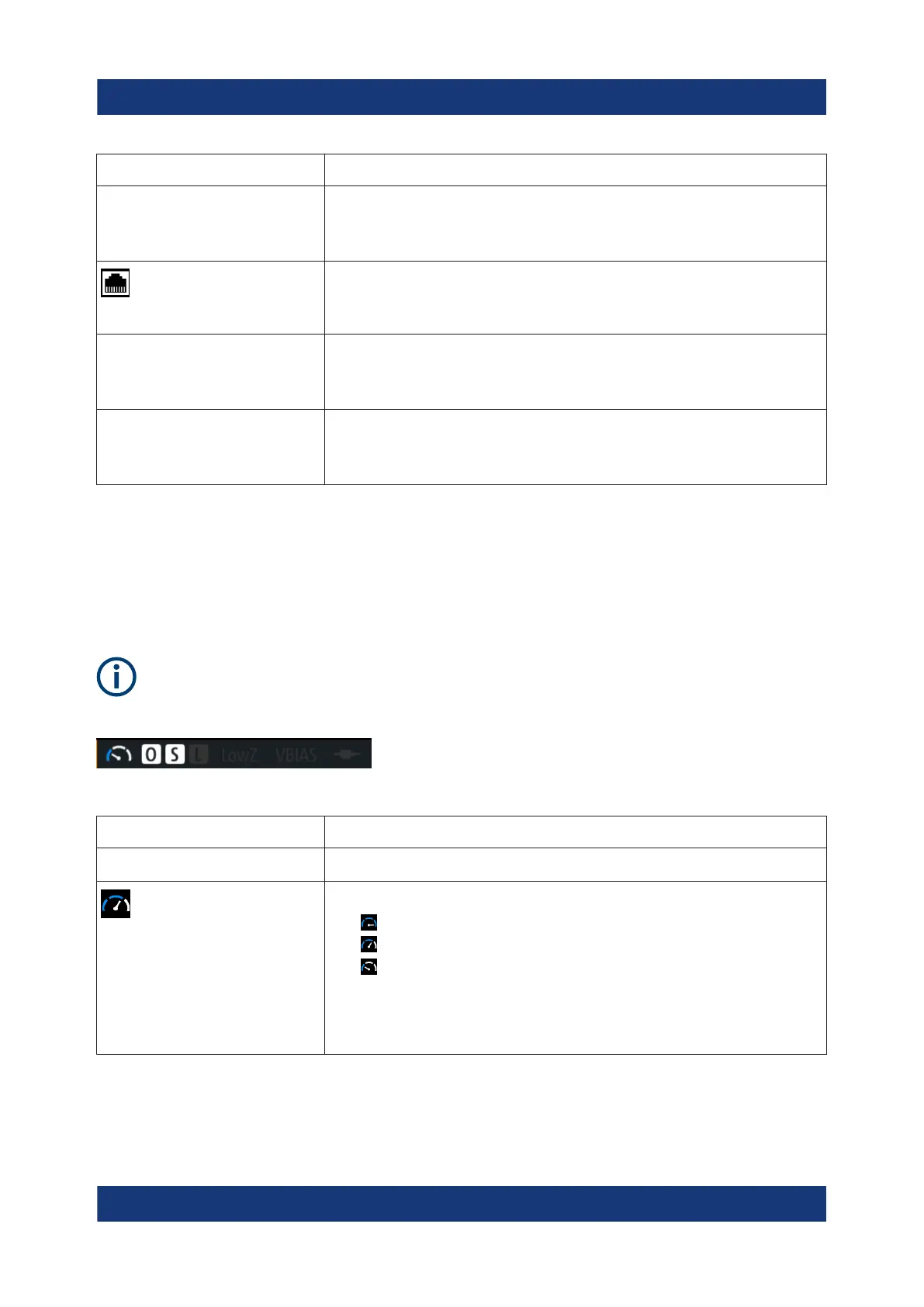
Measurement status bar
The measurement status bar provides information on certain measurement
modes, functions and states. When activated, indicators displayed in white color
represent the corresponding functions.
For information on the measurement modes and functions, see "Instrument
functions > Measurement parameters" in the user manual.
Table 6-2: Measurement status bar
Indicator Description
Measurement mode
Measurement speed
Indicates the set measurement speed:
●
fast
●
medium
●
slow
In triggered mode, the icon is grayed out.
See "Instrument functions > Measurement parameters > Mea-
surement settings > Measurement speed" in the user manual.
Means of manual interaction

 Loading...


