Operating concepts
R&S
®
NRP Series
42Getting Started 1419.0170.02 ─ 16
Setup
NRP
3-Path Diode Power Sensor
MHz to GHz, 100 pW to 200 mW (−70 dBm to +23 dBm)
SMART SENSOR TECHNOLOGY
1
2
3
4
6
5
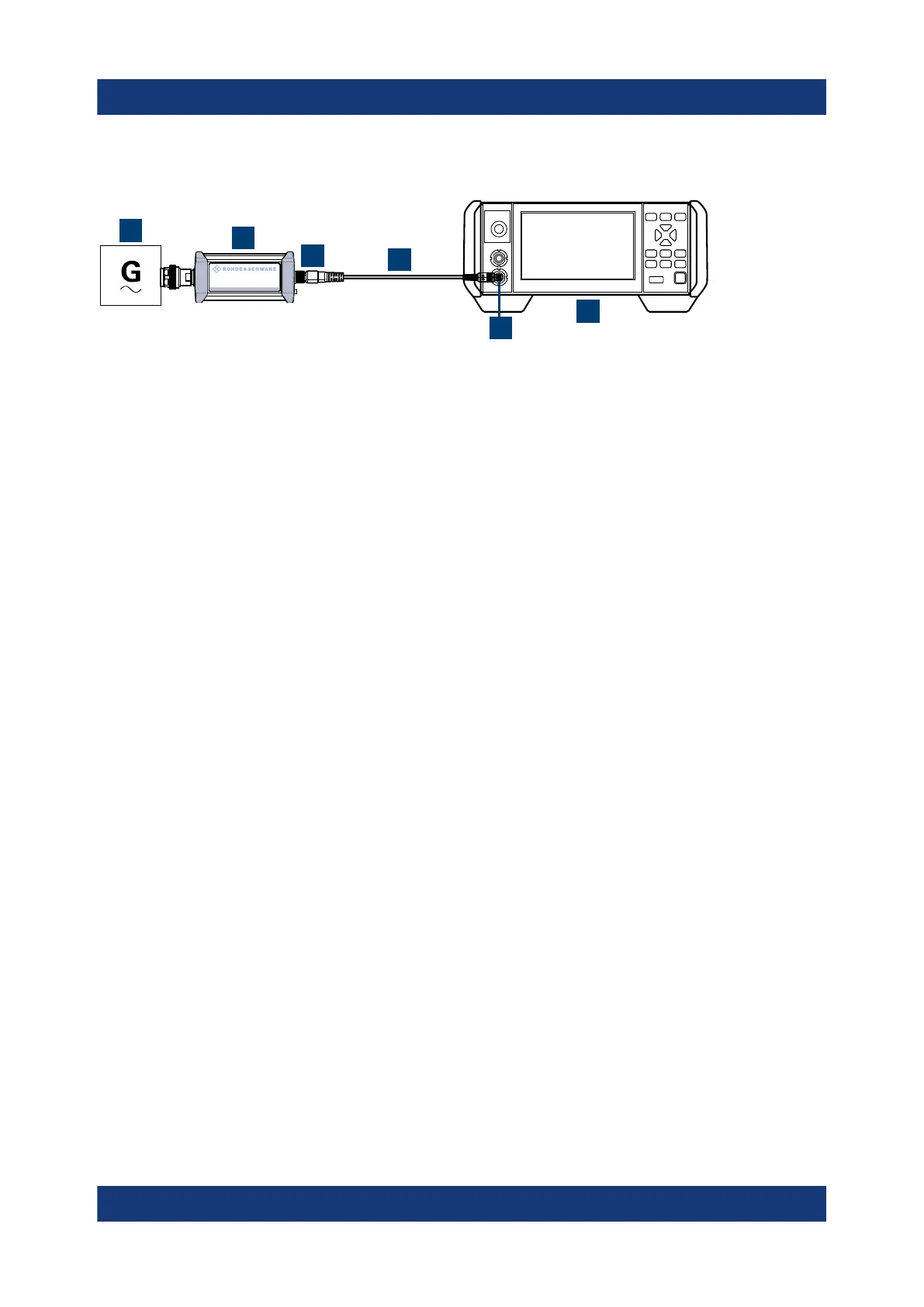
Figure 5-4: Setup with an R&S
NRX base unit
1 = Signal source
2 = R&S NRP power sensor
3 = Host interface connector
4 = R&S NRP‑ZK8 cable
5 = Sensor input connector of the R&S NRX
6 = R&S NRX base unit
1. NOTICE! Incorrectly connecting or disconnecting the power sensor can dam-
age the power sensor or lead to erroneous results. Ensure that you connect or
disconnect the power sensor as described in Chapter 3.4, "Connecting to a
DUT", on page 13.
Connect the power sensor to the signal source.
2. Connect the cables as shown in Figure 5-4.
If the power sensor is a R&S NRP LAN power sensor, you can set up a LAN
connection instead of using the sensor input connector of the R&S NRX. See
Chapter 3.7.3, "Using a LAN connection", on page 20.
Starting a measurement
For a detailed description of how to measure in this setup, refer to the user man-
ual of the R&S NRX.
1. Preset the R&S NRX and the connected R&S power sensors.
a) Press the [Preset] key.
b) Tap "Preset".
All parameters are set to their defaults.
2. Note: Turn off all measurement signals before zeroing. An active measure-
ment signal during zeroing causes an error.
a) Switch off the power of the signal source.
b) Press the [Zero] key of the R&S NRX.
c) Tap "Zero All Sensors".
R&S NRX

 Loading...

