Instrument Tour
R&S
®
ZNLE
43Getting Started 1323.2873.02 ─ 07
Maximum input levels
The maximum input levels at all test ports according to the front panel label-
ing or the data sheet must not be exceeded.
In addition, the maximum input voltages of the other input connectors at the
rear panel must not be exceeded.
It is recommended that you use a torque wrench when screwing RF cables
on the test port connectors.
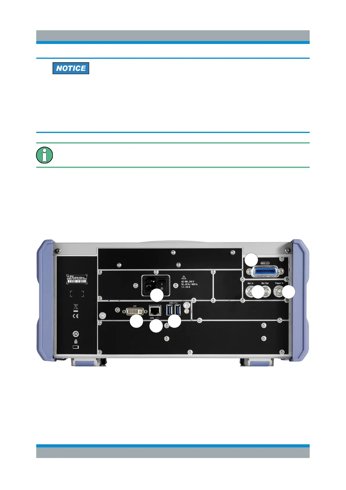
5.2 Rear Panel View
This figure shows the rear panel view of the R&S ZNLE. The individual elements
are described in more detail in the subsequent sections.
1
3
5 7
6
2
4
Figure 5-3: Rear panel view
1 = AC Power Supply Connection and Main Power Switch
2 = GPIB ("IEC") interface
3 = Reference clock connectors
4 = Trigger input connector
Rear Panel View

 Loading...