10 | Gas connection for gas units
80.06.070_iCombi Pro-iCombi Classic_IM_V01_en-GB 71 / 92
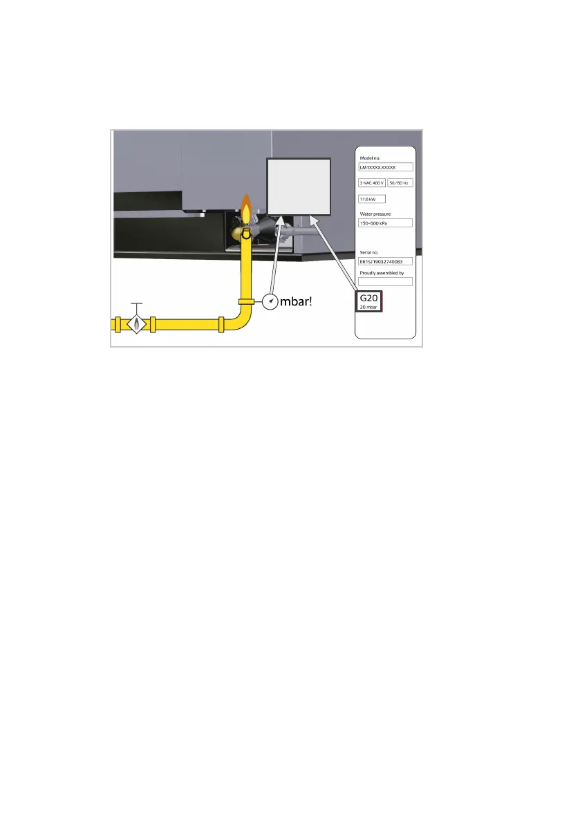
Requirements for gas type and gas pressure
n
Check that the factory gas setting on the unit corresponds to the actual local
gas supply conditions.
n
The gas type and the dynamic connection pressure set on the unit must cor-
respond to those stated on the type plate.
n
If the line pressure deviates from the connection flow pressure of the unit,
contact your gas supply company.
n
Adhere to all local gas company regulations.
Requirements for gas inlet and gas line
n
The exhaust gas analysis may only be carried out by a technician who is au-
thorised by the manufacturer. The exhaust gas analysis must be carried out
before commissioning.
n
Gas connections must only be set up by locally authorised gas technicians.
n
The gas connection line must be set up in accordance with the rated thermal
load specified on the type plate.
n
Use a suitable gas leak detector to check for leaks in the gas supply and gas
distribution within the unit.
n
The cross-section of the gas line must be designed to the maximum con-
nected output of all loads, at least ¾ inch.
n
A gas shut-off valve must be installed in front of every unit.
n
All connection components installed on-site must be checked in accordance
with DIN-DVGW (local gas supply company).
n
It is possible to connect the gas line with a gas socket.
n
A connection with an internal thread is necessary to connect the gas line.
n
The unit must be protected against slipping.
n
If undiluted CO levels are above 174.7 mg/m³ [150 ppm] for convection
mode and 465.8 mg/m³ [400 ppm] for steam mode, a company-trained
and certified technician must be called in to check burner settings in accord-
ance with setting instructions, and adjust these settings if needed. A flue gas
analysis must then be performed by the technician.
n
Follow the maintenance instructions for gas components.
n
The gas installation must meet the CGA-B 149.1 natural gas regulation or
the CGA-B 149.2 propane gas regulation.
 Loading...