5 | Placement
80.06.070_iCombi Pro-iCombi Classic_IM_V01_en-GB 27 / 92
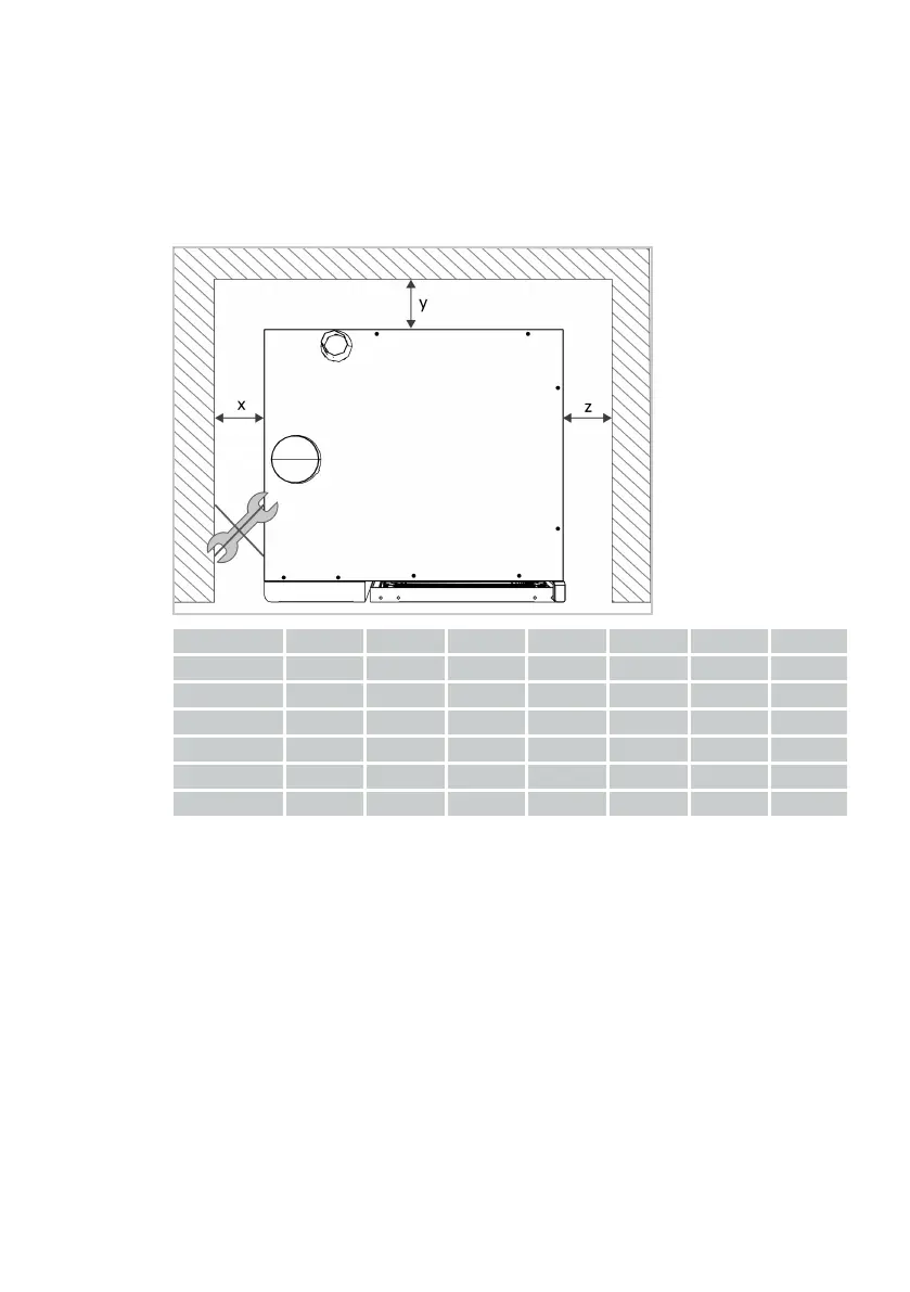
5.1 Minimum clearance to unit
5.1.1 Distance to walls
Minimum clearance on all sides
Place the unit in consideration of the minimum clearance to the wall. The clear-
ances depend on the unit size, as shown in the following table.
Unit size 6-2/3 6-1/1 6-2/1 10-1/1 10-2/1 20-1/1 20-2/1
x (mm) 10 50 50 50 50 500 500
x (inch) 1/2 2 2 2 2 20 20
y (mm) 10 0 0 0 0 0 0
y (inch) 1/2 0 0 0 0 0 0
z (mm) 10 50 50 50 50 50 50
z (inch) 1/2 2 2 2 2 2 2
Recommended clearance on left side of the unit
Place the unit with a minimum recommended clearance to the wall on its left to
ensure sufficient space on the left side of the unit to perform servicing works at
the installation site.
 Loading...