INSTRUCTION, USE AND
MAINTENANCE MANUAL
GB
Page 13 of 60
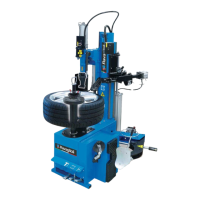
Fig. 5
a=762 mm
b=525 mm
c=410 mm
• Execute 4 holes with 8 mm diameter on the floor by
the holes on the bottom floor;
• insert the small blocks (excluded from supply) into
the holes;
• fix the machine to the ground with 4 M8x80 mm
screws (excluded from supply) (Fig. 5 ref. 1) (or
with 4 8x80 mm stud bolts (excluded from supply)).
Tighten the screws with an approximate tightening
torque of 70 Nm.
9.2 Fixtures contained in the packing
The packing case contains also the fixtures box. Check
that all the parts listed are there.
Code Description N.
203193 VTE M10x30 4
228012 M10 self-locking nut 4
203074 VTE M12x35 4
237025 Flat washer 12x25x2,5 8
228014 M12 self-locking nut 4
B4064201 Vane 1
140925901 Screw for bead-breaker arm 1
228006 M12 self-locking nut 1
237069 Flat washer 2
903090 Ball knob D. 40 1
253017 Belleville washer 1
730022630 Tank bracket 1
272019 TE M6x16 screw 4
228206 Crated nut M6 4
RAVAGLIOLI S.p.A.
7300-M018-2_R
G8945.26 - G8945IT.26 - G8945V.26 - G8945ITV.26 - G8945V.26S - G8945ITV.26S - G8945D.26 - G8945ITD.26 - G8945D.26S - G8945ITD.26S
9.3 Assembly procedures
Lifting device installation
Only for G8945V.26S - G8945ITV.26S -
G8945D.26S - G8945ITD.26S models)
1. After placing the tyre-changer in the working place
and after making sure it is insulated from its power
supply sources, proceed with the fastening of the
lifting device.
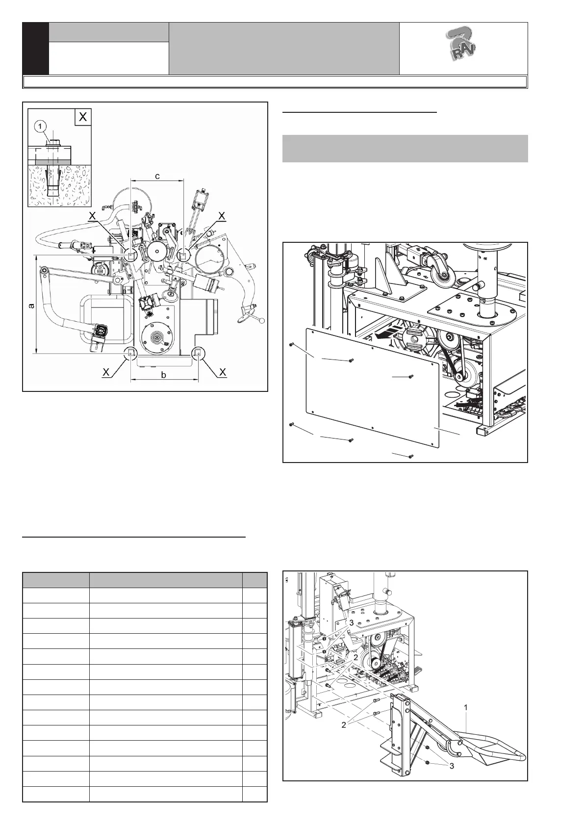
2. Remove the lateral carter (Fig. 6 ref. 1) by unscrew-
ing the relevant screws (Fig. 6 ref. 2).
1
2
2
2
2
Fig. 6
3. Place the lifting device that is assembled next to the
tyre-changer on which it will be installed.
4. Prepare and arrange near the screws and the ac-
cessories, which are necessary for fixing the lifting
device to the tyre-changer.
5. Fix the lifting device (Fig. 7 ref. 1) to the tyre changer
using the screws (Fig. 7 ref. 2) (# 203193) and the
nuts (Fig. 7 ref. 3) (# 228012) on issue.
Fig. 7
 Loading...