Cab Component Installation: Routine Operation 39
CAB COMPONENT INSTALLATION
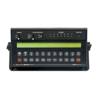
FIGURE 25. Cable Routed to RS1
5. Plug the 12-pin connector into the mating connector on the RS1.
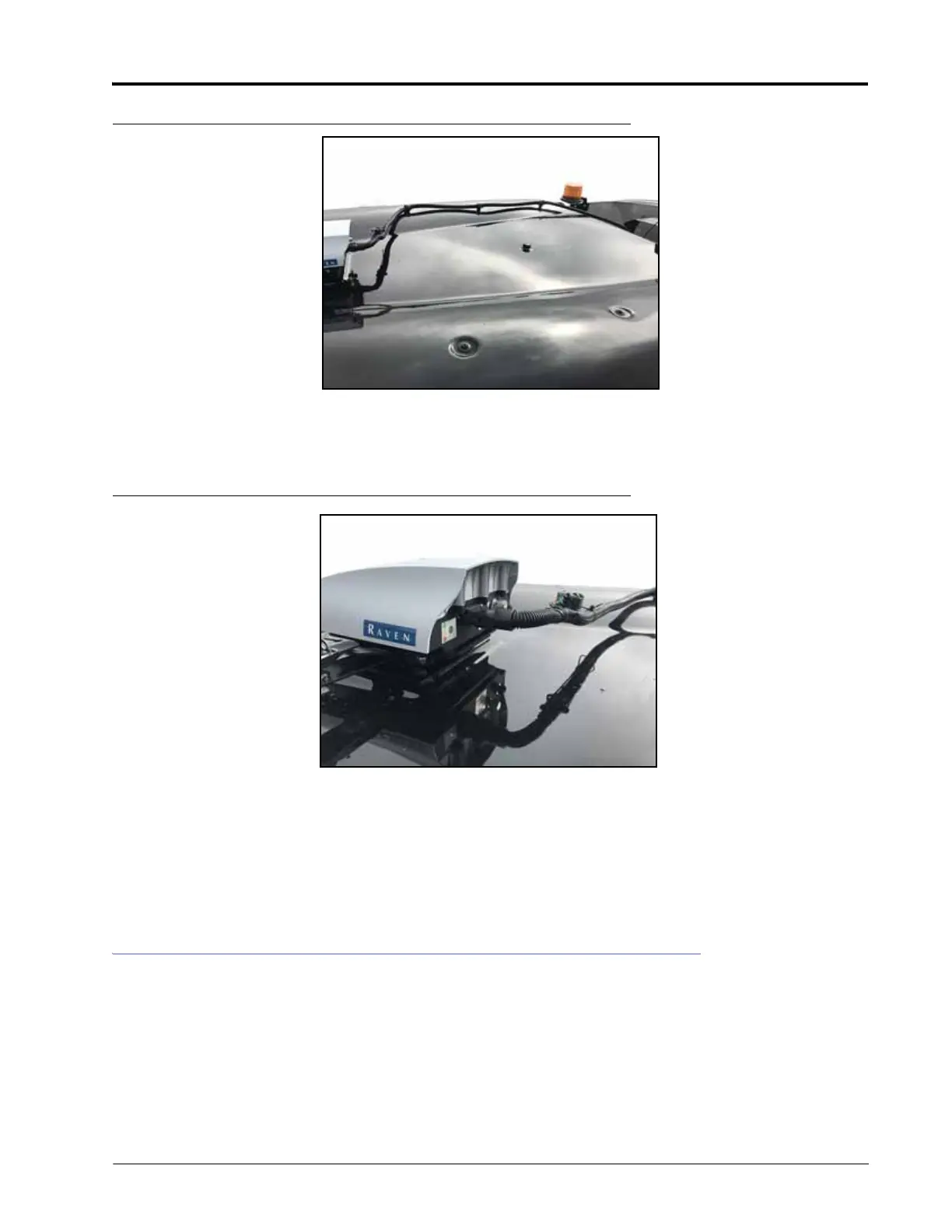
FIGURE 26. 12-Pin Connected to RS1
NOTE: The 4-pin connector on the RS1 cable will not be used. Leave the dust cap on the connector.
NOTE: If an ISO bed is on the machine, remove the terminator on the RS1 cable and plug the terminator
connector into the provided dust cap. If an ISO bed is not being utilized, leave the terminator on the
cable.
ROUTINE OPERATION
Locate and identify the machine’s master switch on the control panel and the resume switch on the joystick as they
are required for RS1 system operation.
 Loading...