Wuhan Raycus Fiber Laser Technologies Co., Ltd.
User Guide of RFL-C100~RFL-C2000S
27
Each pin is defined as shown in Table 8 below.
Table 8 SERVICE definition
Remote switch (key), passive
contact, can’t be connected to
external voltage or ground
Passive contact, can’t be connected
to external voltage or ground.
Short the pin 6 and 7 before
emission laser
Other pins are empty.
The SERVICE connector is a female DB9 interface. If PIN 6-7 are disconnected, the
laser will immediately stop working, and the laser Ready signal will go low.
The laser has pre-shorted the 6 and 7 pins before shipment. If it is not connected, the
InterLock error will be displayed after the laser is powered on.
CAUTION: The interlock cannot be connected to active signal, or error
will be caused, or even the product may be damaged.
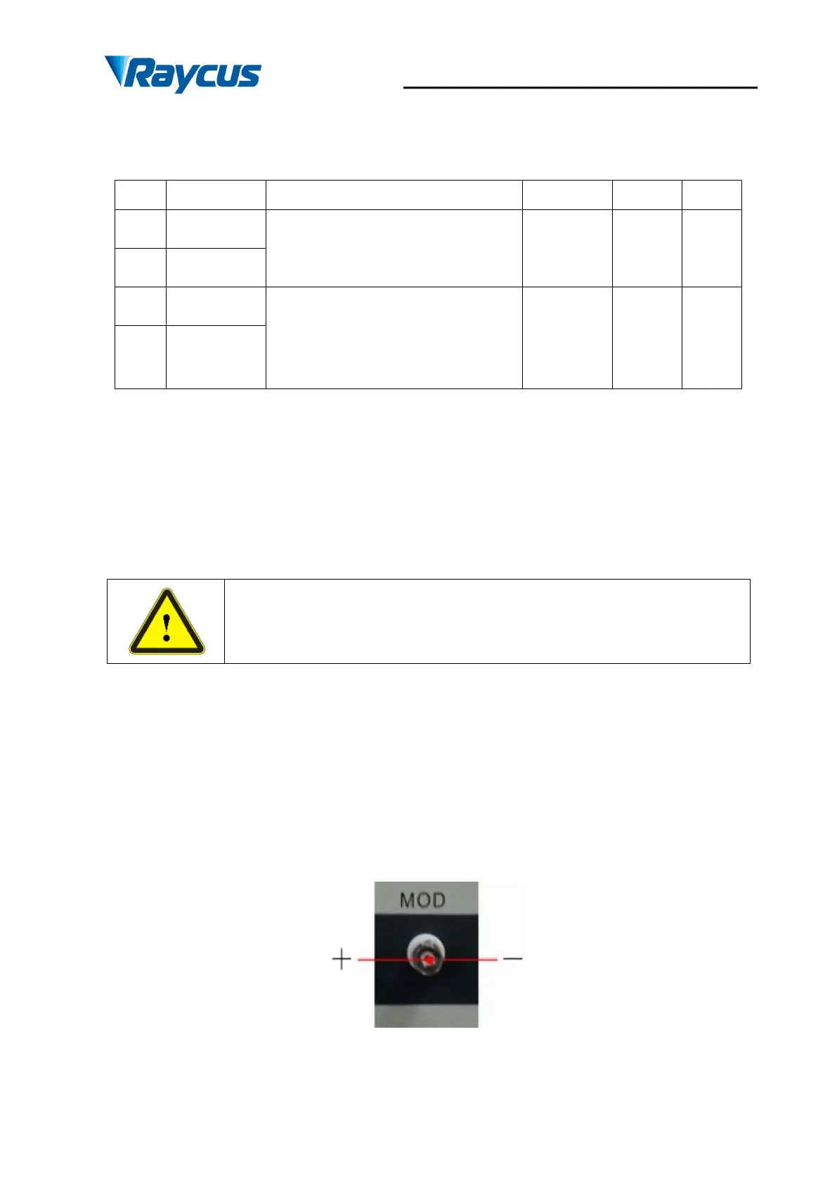
4.4.2 Modulation Input
The 24V modulation signal should be applied to the connector as in Figure 14. A cable is
provided for the connector, which is shown in Figure 15. The MOD modulation signal
description is shown in Table 9, and the internal circuit of the modulation signal is as shown in
Figure 16.
Figure 14 Modulation Input