EasyManuals Logo
Home>Raycus>Measuring Instruments>RFL-C2000

Raycus RFL-C2000 User Manual

Raycus RFL-C2000
49 pages
To Next Page IconTo Next Page
To Previous Page IconTo Previous Page
Page #33 background imageLoading...
Page #33 background image
Wuhan Raycus Fiber Laser Technologies Co., Ltd.
User Guide of RFL-C100~RFL-C2000S
29
PIN
Name
In/Out
Function
Example
min
max
Current
6
LASER
EN
Input
Enable signal
enable
24V
15V
28V
<8mA
disable
0V
0V
3V
7
ADEN
Output
External AD model enable
enable
24V
15V
28V
<8mA
disable
0V
0V
3V
8
Laser
Ready
Output
Ready signal
Ready
24V
<100mA
Not
Ready
0V
9
EXGND
Reference GND of pin
6,7,8,20,24
20
EXVCC
24Vpower for PIN8 and
PIN24
24V
20V
28V
<500mA
22
Analog
Input
Analog Voltage Signal
0V
10V
<10mA
23
Laser
Power
Output
Power indication
0V
5V
<20mA
24
Alarm
Output
Fault Signal
Fault
24V
<100mA
normal
0V
25
AGND
GND of PIN20PIN23
other
NC
None
CAUTION
Please check the control voltage level and ensure that the level is in
accordance with the requirements. Over voltage and voltage ripple
may damage the product.
Make sure that the analog voltage signal does not exceed 10V,
otherwise the product may be damaged.
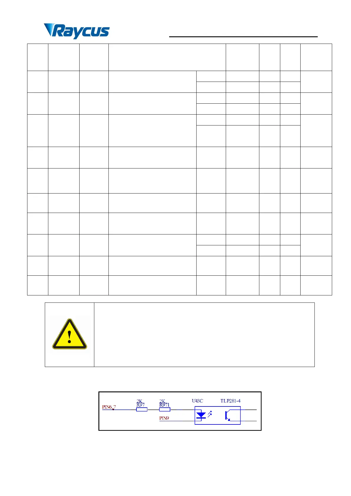
1) PIN6 and PIN7 internal circuit
Figure 18 PIN6PIN7internal circuit
2PIN8 and PIN24 internal circuit

Questions and Answers:

Question and Answer IconNeed help?

Do you have a question about the Raycus RFL-C2000 and is the answer not in the manual?

Raycus RFL-C2000 Specifications

General IconGeneral
BrandRaycus
ModelRFL-C2000
CategoryMeasuring Instruments
LanguageEnglish

Related product manuals