4.3P
owerconnection
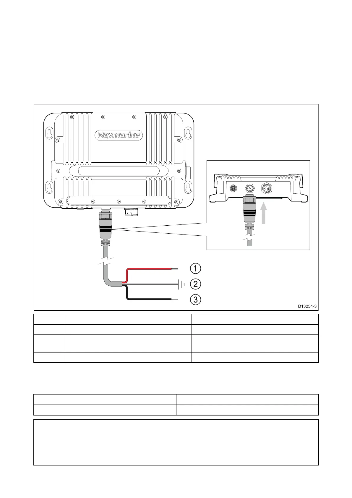
Powermustbesuppliedtothesonarmodulefromanappropriatepowersource.
Powerconnectionrequirements
•12or24Vdcnominalsupplyvoltage
•Isolatedpowersupply
•Connectedviaanappropriatelyratedthermalbreakerorfusedswitch.Referto:In-linefuse
andthermalbreakerratings.
DescriptionConnectsto:
1
R edcable(positive)
Powersupply’spositiveterminal.
2
Drain/Ground
V
esselRFground,ornegativebattery
terminal
3
Blackcable(negative)
P owersupply’snegativeterminal.
In-linefuseandthermalbreak erratings
Thefollowingin-linefuseandthermalbreakerratingsapplytoyourproduct:
In-linefuseratingThermalbreak errating
5Aslowblow
5A(ifonlyconnectingonedevice)
Note:
•Thesuitablefuseratingforthethermalbreak erisdependentonthenumberofdevicesyouare
connecting.IfindoubtconsultanauthorizedFLIRdealer.
•Y ourproduct’spowercablemayhaveafittedin-linefuse,ifnotthenyoucanaddanin-linefuse
tothepositivewireofyourproduct’spowerconnection.
48

 Loading...