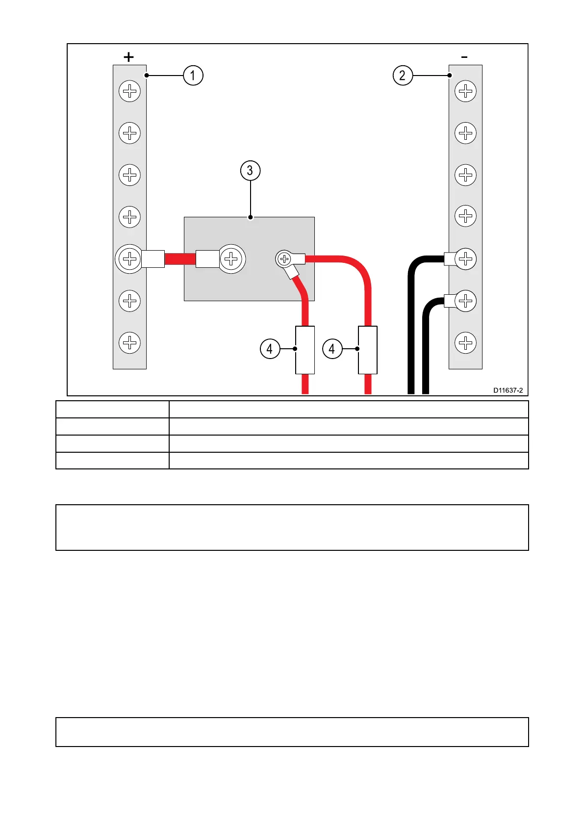
1
P ositive(+)bar
2
Negative(-)bar
3Circuitbreak er
4Fuse
•Inallcases,observetherecommendedbreak er/fuseratingsprovidedintheproduct’s
documentation.
Important:
Beawarethatthesuitablefuseratingforthethermalbreak erorfuseisdependentonthenumber
ofdevicesyouareconnecting.
P owercableextension
Ifyouneedtoextendthelengthofthepowercablesuppliedwithyourproduct,ensureyouobserve
thefollowingadvice:
•Thepowercableforeachunitinyoursystemshouldberunasaseparate,singlelengthof2-wire
cablefromtheunittothevessel'sbatteryordistributionpanel.
•Forpowercableextensions,aminimumwiregaugeof16AWG(1.31mm
2
)isrecommended.For
cablerunslongerthan15meters,youmayneedtoconsiderathickerwiregauge(e.g.14AWG
(2.08mm
2
),or12AWG(3.31mm
2
)).
•Animportantrequirementforalllengthsofpowercable(includinganyextension)istoensurethat
thereisacontinuousminimumvoltageattheproduct’spowerconnectorof10.8Vdc,witha
fullyflatbatteryat11Vdc.
Important:Beawarethatsomeproductsinyoursystem(suchassonarmodules)cancreatevoltage
peak satcertaintimes,whichmayimpactthevoltageavailabletootherproductsduringthepeaks.
Grounding
Ensurethatyouobserveanyseparategroundingadviceprovidedintheproduct’ sdocumentation.
Cablesandconnections51

 Loading...