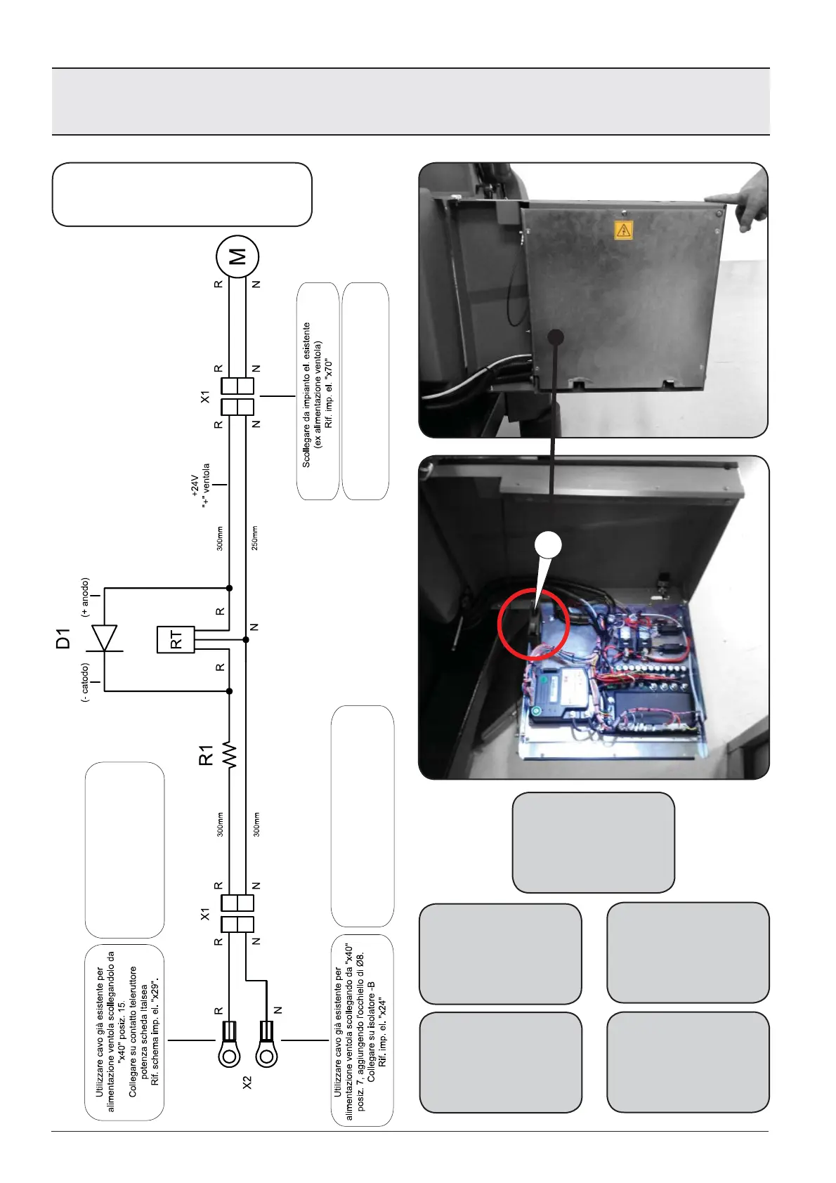
101
Disconnect the fan wire supply wire
from “x40” pos.15 and connect it to
the (Italsea) power contactor.
Ref. electric diagram “x29”
Disconnect the fan wire supply from “x40”
pos.7, adding the Ø8 terminals.
Connect to the insulator -B
Ref. electric diagram “x24”
Disconnect from the electric system
(ex. fan supply)
Ref. electric diagram “x70”
M
SCHEMA VENTOLA
FAN DIAGRAM ESQUEMA VENTILADOR
SCHÉMA DU VENTILATEUR VENTILATORSCHEMA
M. Elettroventola 24V
R. Resistenza 100Ω
RT. Regolatore di tensione
D1. Diodo N4007
X1. Connettore 2 Vie M/F
X2. Capocorda Ø8
M. 24V Fan
R. 100Ω Resistor
RT. Voltage regulator
D1. Diode ( N4007 )
X1. MF 2-Way connector
X2. Terminal Ø8
M. Ventilador 24V
R. Resistencia 100Ω
RT. Regulador de tensión
D1. Diodo N4007
X1. Conector de 2 vías M/F
X2. Terminal ojal Ø8
M. Ventilateur électrique 24V
R. Résistance 100Ω
RT. Régulateur de tension
D1. Diode N4007
X1. Connecteur 2 voies M/F
X2. Cosse à oeil Ø8
M. Elektrische ventilator 24V
R. Weerstand 100Ω
RT. Spanningsregelaar
D1. Diode N4007
X1. M/V 2-Weg connector
X2. Kabelschoenen Ø8
Da matricola / From SN / A partir del número de serie
A partir du numéro de série / Van serienummer:
232356