Real Clean System I v 2.1
Real Tech Inc. 10
5.5 Electrical and Communication
The power and communication line from the M Series
analyzer feeds into the Real Clean system via an
electrical conduit fitting at the bottom of the cabinet. The
system is powered and controlled through the
connected M series analyzer.
Connections at the M Series Analyzer are shown in
Figure 5.7.
• White and green wires to terminal 7 and 8 (Clean
Out). Polarity is not important.
• Black wire to terminal 9 (24 VDC Out -).
• Red wire to terminal 10 (24 VCD Out +).
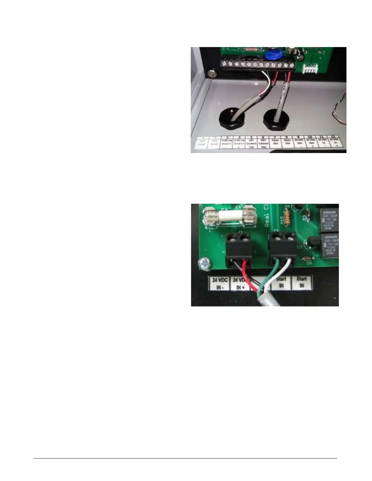
The terminal block connections at the Real Clean
system control board are shown in Figure 5.8.
1. Connect the white and green wires leading from
the M Series analyzer to the right terminal
block. Polarity is not important.
2. Connect the power wires leading from the M
Series analyzer to the left terminal block. The
black power wire connected to the left (-)
terminal and red wire to the right (+) terminal.