13
8. Machine Assembly - Cont.
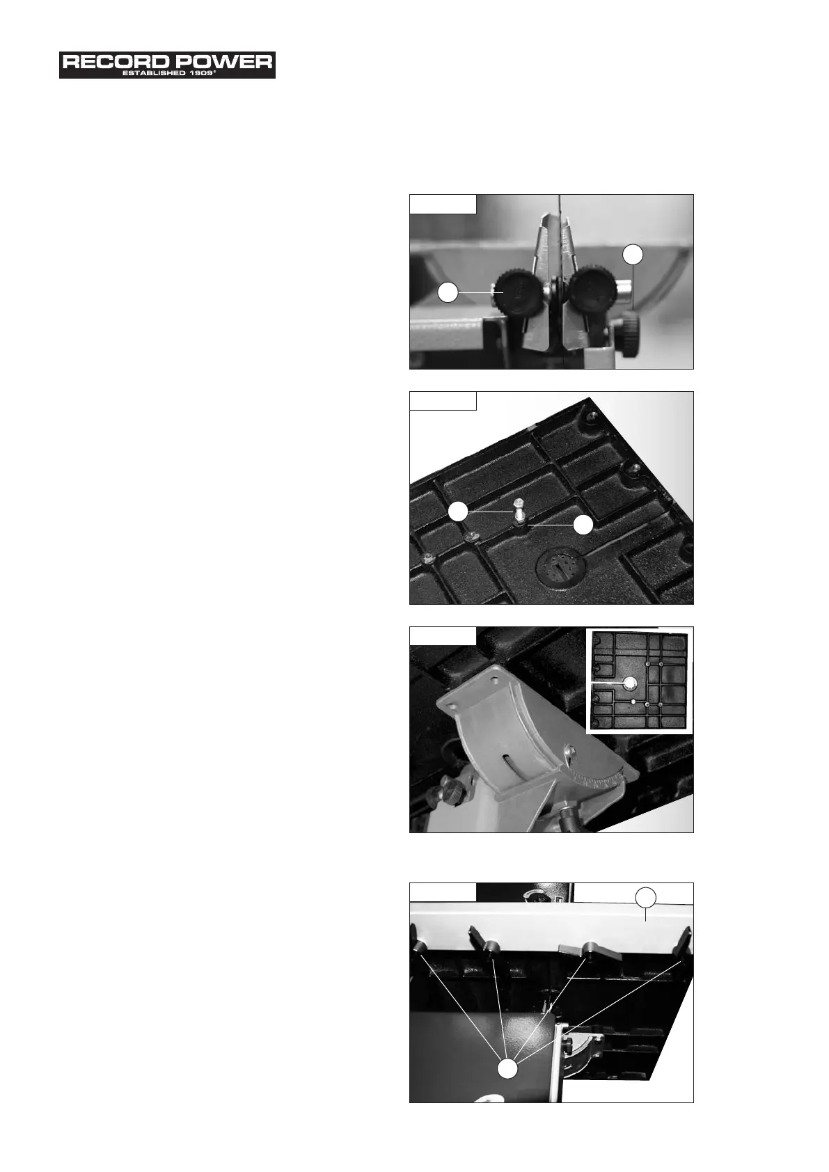
After removing the machine it is advisable to make an
initial setting to the lower blade guides. Open the lower
door, using a flat blade screwdriver to undo the door locks
and slacken the two blade guide locking knobs (Fig. 8.1,
A), then position the guides to within 0.5 mm of the blade.
Adjust the rear thrust guide by loosening the locking knob
(Fig. 8.1, B) so that it is just clear of the back of the blade.
Fitting the table
First, turn the table upside down and fit the M6 x
30 mm hex head screw and M6 nut (Fig 8.2, A) in the
threaded hole in the underside of the table (Fig 8.2, B).
This acts as the table stop at 90º
and will need to be
adjusted once the table is fitted (described later in this
section). Position the table on the trunnion of the machine,
aligning the holes in the trunnion with the fixing holes in
the underside of the table (Fig 8.3). Secure with the 4 M6
x 15 mm hex head screws and 4 serrated
washers supplied.
Fitting the Fence Rail
1. Take the four wing nuts and washers (Fig. 8.4, A) and
fit them into the threaded holes on the underside of the
table. But do not fully tighten.
2. Slide the fence rail (Fig. 8.4, B) into the gap left between
the table and the wing bolt (Fig. 8.4, A) then tighten the
wing bolt to secure the fence rail.
Fig. 8.1
A
Fig. 8.2
A
B
B
Fig. 8.3
1
4
2
3
1
4
2
3
Fig. 8.4
A
B