11.2 Replacing the drive belt
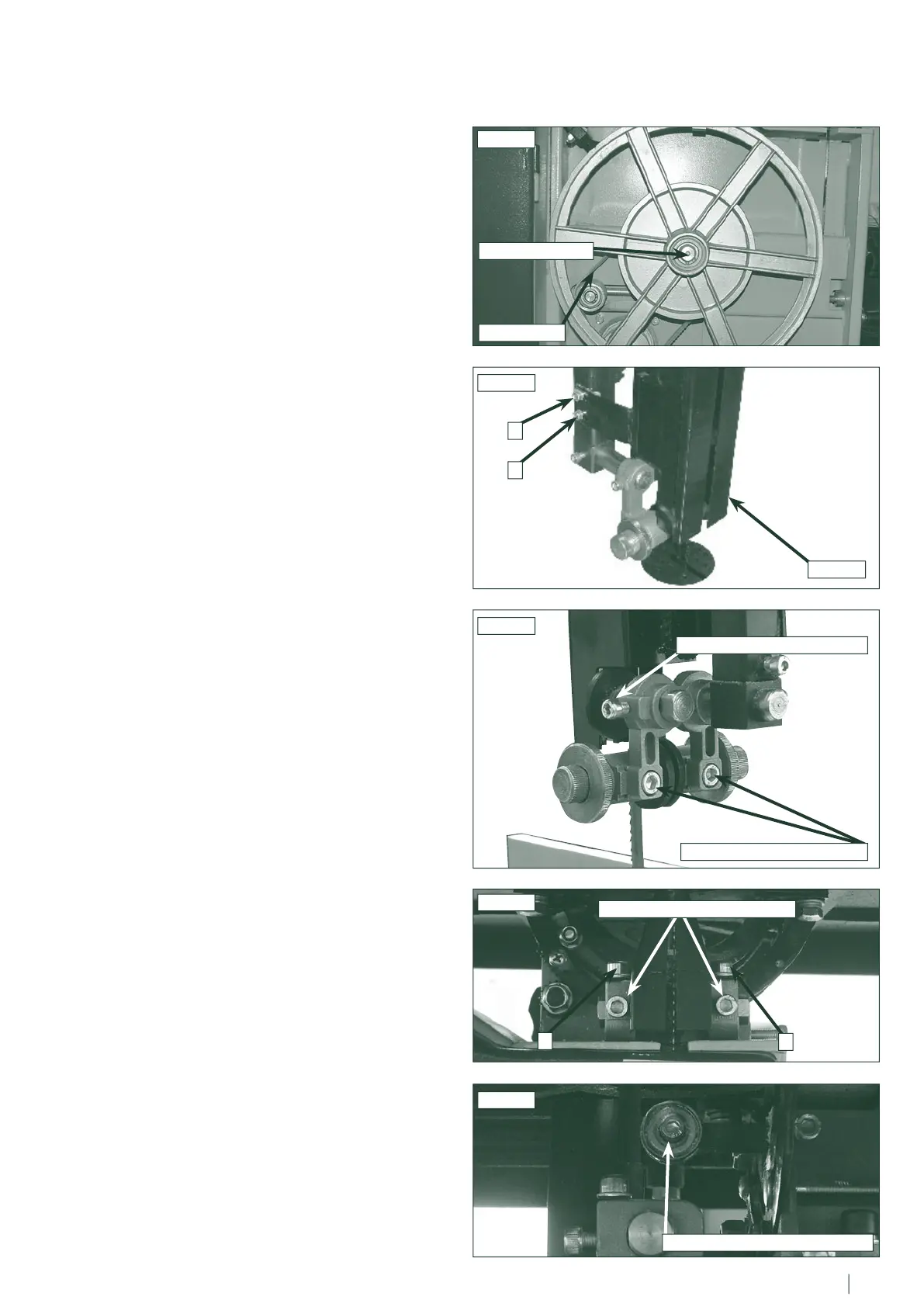
To replace the drive belt first remove the lower bandwheel by
undoing the 13mm nut on the hub. Then simply loosen the
tension on the belt using the tension handwheel, remove the old
belt and fit the new one Fig.11.4. Once the drive belt is in place
re-fit the lower bandwheel and tighten the nut. Now tension the
drive belt using the tension handwheel. For further information
on tensioning the drive belt please see section 7.1.
11.3 The blade guide system
In general usage it is advisable to carefully apply silicon spray
to the blade guides to ensure free movement of the rollers,
do not use oil or grease for lubrication as this will attract dust
and cause the rollers to jam. The blade guide system is a
consumable item and depending on usage will wear and need
replacing.
When replacing components on the upper guide assembly first
ensure that the blade is removed. Undo hex nuts A & B then
remove the guard. Fig.11.5. Once the guard is removed then
the various components can be accessed and replaced. Undo
the relevant hex nuts for either the guide rollers or rear thrust
pad Fig.11.6. and fit the new parts. Once the new components
are fitted. The blade should be re-fitted Section 11.1 and the
guides adjusted as shown in Section 6.3.
When replacing components on the lower guide assembly first
ensure that the blade is removed. Undo hex nuts C & D and
remove the guards. Fig.11.7. Once the guard is removed then
the various components can be accessed and replaced. It is
necessary to only replace the roller bearings on either side
Fig.11.7. or the thrust roller bearing at the rear Fig.11.8. This
is done by simply undoing the relevant hex head screw and
replacing the part. Once the new components are fitted. The
blade should be re-fitted Section 11.1 and the guides adjusted
as shown in Section 6.3.
CAUTION!
Before carrying out any adjustments or maintenance
ensure that the machine is isolated and disconnected
from the electricity supply.
Fig.11.4
13mm HUB NUT
DRIVE BELT
Fig.11.5
Fig.11.6
GUARD
GUIDE ROLLER HEX NUTS
THRUST ROLLER HEX NUT
Fig.11.7
Fig.11.8
A
B
C
D
SIDE ROLLER HEX SCREWS
THRUST ROLLER HEX SCREW
11. Maintenance - cont.
26 27