11. Maintenance
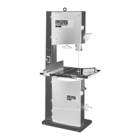
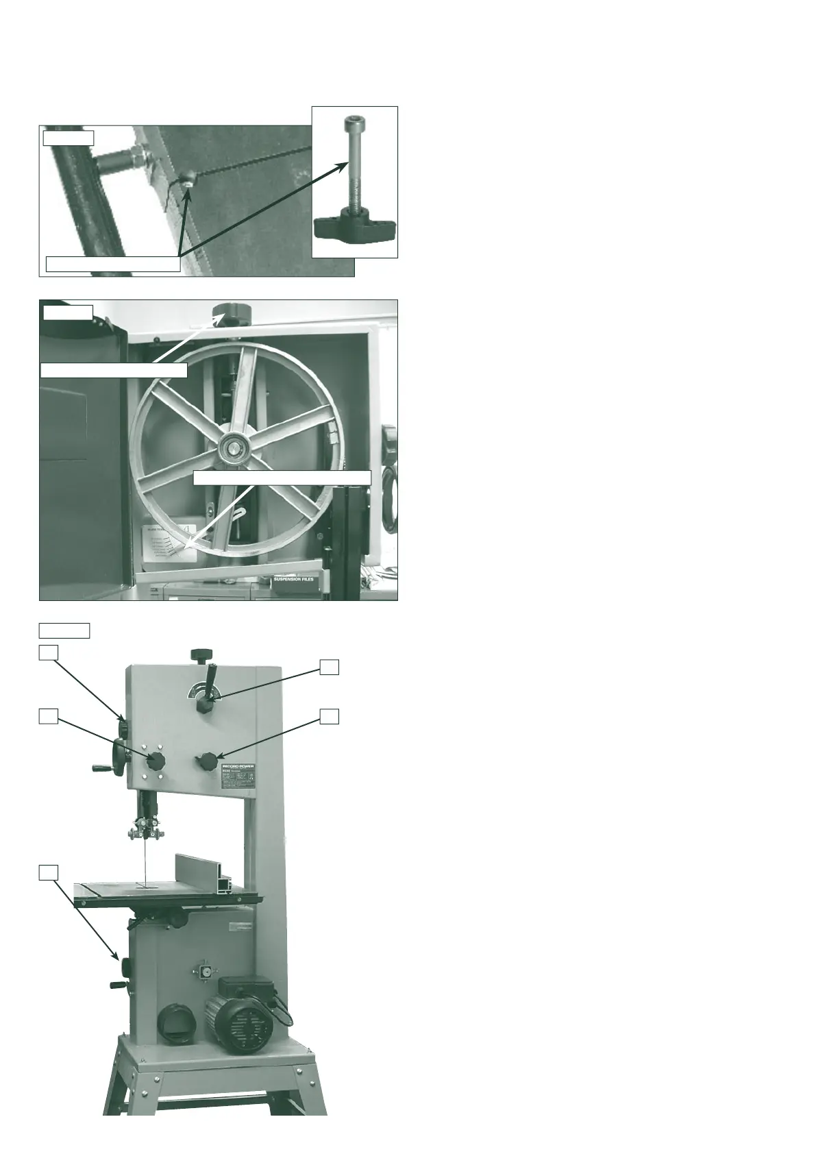
BLADE TENSION INDICATOR
BLADE TENSION KNOB
17
15
16
14
14
11.1 Replacing the bandsaw blade
HAZARD!
Take great care when unpacking the bandsaw blade
as they are usually folded and can spring out very suddenly with
great force.
TIP: If the new blade being fitted is a different width to the one
being removed, it is advisable to move back and slacken off all
blade guides before fitting the new blade as this will make fitting
easier. Whenever a different size blade is fitted the blade guides
will always need re-setting.
1.
Isolate the machine from the power supply.
2. Open the top and bottom bandwheel doors by turning the
star handle
Fig 11.3 (14).
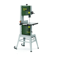
4.
Remove the Hex socket screw, bushing and wing nut
fitted to the front of the table
Fig 11.1
.
5.
Move the lever clockwise to
release the blade tension
. Fig
11.3 (17)
.
6. Remove the bandsaw blade by feeding it through the
slot in the table, upper blade guides & guard and slot in
the spine of the machine taking care not to cut yourself,
wear gloves if necessary.
7a. If the new blade being fitted is a different width to the
one being removed, before the new blade is placed
around the bandwheels:
• Re-apply the cam handle moving the bandwheel
upwards. Now adjust the tension wheel to suit the new
blade size.
• Once the tension indicator is showing the correct
reading for the new blade release the cam handle
and place the new blade on the bandwheels.
• When fitting the new blade ensure the blade teeth are
pointing downwards and towards you at the position
where the blade passes through the table.
•
Ensuring that the blade is fully in place on bandwheel,
re-apply tension using the cam handle.
• Fine adjust the blade tension further if required using the
blade tension wheel.
7b. If the new blade width is the same as the blade being
removed:
• Fit the new blade ensuring the blade teeth are pointing
downwards and towards you at the position where the
blade passes through the table.
• Ensuring that the blade is fully in place on bandwheel.
Simply re-apply tension using the cam handle lever.
• Fine adjust the blade tension further if required using the
blade tension wheel.
8.
Check the blade tracking on the newly fitted blade by
turning the upper wheel by hand. The blade should run
as close to the centre of the bandwheel as possible.
On 1/4", 3/8" and 1/2" blades it may be necessary to run
the blade to rear of the bandwheel
(see section 6.2.)
9. If required adjust the tracking using tracking knob
(15)
and
lock knob to the rear of the upper bandwheel housing.
When the tracking is correct lock the settin
g (see section
6.2)
.
10.
Re-set the blade guides
(see sections 6.3 & 6.4)
11. Close and lock both the bandwheel doors before re
connecting the power supply.
The blade tension indicator is a guide only and may need
re-calibrating periodically. For further information on blade
tensioning
see section 6.1
.
CAUTION!
Before carrying out any adjustments or maintenance
ensure that the machine is isolated and disconnected
from the electricity supply.
Fig.11.1
Fig.11.2
HEX SOCKET SCREW
Fig.11.3