10
Fig.3.3
Fig.3.4
Fig.3.5
Fig.3.6Fig.3.2
Fig.3.7
LONG TOP BRACE
SUPPORT
SHORT TOP BRACE
SUPPORTS
LONG MID BRACE
SUPPORT
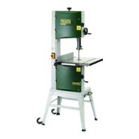
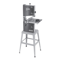
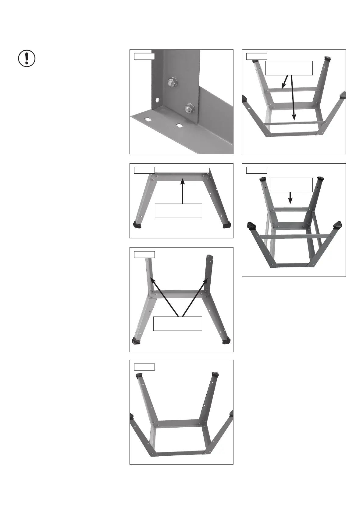
3. Stand & Wheel Kit Assembly
SHORT MID
BRACE SUPPORT
Note: When assembling this legstand do
not fully tighten the nuts and bolts until
the assembly is complete.
When fitting the optional pedal wheekit
during initial assembly of the bandsaw,
please do so before attaching the
bandsaw to the leg stand to ensure
greater safety and ease of fitment.
When fitting the optional pedal wheelkit,
the short mid brace support (Fig. 3.7) at
the front of the bandsaw should
be removed.
Please see section 15 for assembly
instructions of the BS350S-W Pedal
Wheel Kit.
3.2 Stand Assembly
1. Locate the first leg and secure it to one of the
long top brace supports using the nuts, bolts and
washers supplied Fig.3.2.
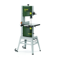
2. In the same way, attach the second leg to the
brace support Fig.3.3.
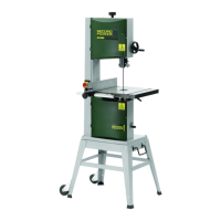
3. Locate the short top brace supports and fix
them to the legs as shown Fig.3.4.
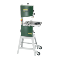
4. Continue in this way until all of the legs and
top brace supports have been fitted Fig.3.5.
5. The locating holes a third of the way down
each leg are for securing the mid brace supports.
Fix the long mid brace supports to the frame
using the nuts, bolts and washers Fig.3.6.
6. Finally, fit the short and medium mid brace
supports to the shorter sides Fig.3.7. The short
mid brace support is fitted to holes positioned
two thirds of the way up each leg. The medium
mid brace support is positioned in the lower
holes in each leg.